Page 3 - WARNING! Read and understand all instructions.; SAVE THESE INSTRUCTIONS; Keep your work area clean and well lit.; More Not more
English 1 IF YOU HAVE ANY QUESTIONS OR COMMENTS ABOUT THISOR ANY D E WALT TOOL, CALL US TOLL FREE AT: 1-800-4-DEWALT (1-800-433-9258) General Safety Instructions WARNING! Read and understand all instructions. Failure to follow all instructions listed below, may resultin electric shock, fire and/or s...
Page 4 - English; Do not force tool. Use the correct tool for your application.
English 2 PERSONAL SAFETY• Stay alert, watch what you are doing and use commonsense when operating a power tool. Do not use tool whiletired or under the influence of drugs, alcohol, or medica-tion. A moment of inattention while operating power tools may result in serious personal injury. • Dress pro...
Page 6 - COMPONENTS; C. Spindle Lock Button; ASSEMBLY; CAUTION: Turn off and unplug the tool before making any
English 4 • The label on your tool may include the following symbols. Thesymbols and their definitions are as follows: V ..........volts A ..........amperes Hz ............hertz W ..........watts min ..........minutes ..........alternating current ........direct current no ..........no load speed .....
Page 8 - CAUTION: Use a Type 27 guard with wire brushes and; Operators and others in the area should wear appropriate
English 6 Wire Wheels 3" wire cup brush 4" wire wheel Type 27 guard Type 27 guard rubber backing pad sanding disc threaded clamp nut Sanding Discs (DW831) Sanding Flap Discs Type 27 guard hubbed sanding flap disc Type 27 guard unthreaded backing flange non-hubbed sanding flap disc threaded c...
Page 9 - Edge grinding and cutting can be performed only with; Sanding With Abrasive Discs; PERSONAL SAFETY
English 7 Grinding Using a depressed center Type 27 wheel,hold the tool at an angle of approximately10˚- 30° to the work for grinding. MostType 27 wheels are not designed for cut-ting operations. Edge Cutting WARNING: Edge grinding and cutting can be performed only with Type 27 wheels that are desig...
Page 10 - ENVIRONMENTAL SAFETY; Unplug the tool before mounting or removing the; FITTING GUARD; Do not operate grinder with a loose guard or the
English 8 2. A dust mask or respirator should be worn by all persons enter- ing the work area. The filter should be replaced daily or when-ever the wearer has difficulty breathing. NOTE: Only those dust masks suitable for working with lead paint dust and fumes should be used. Ordinary painting masks...
Page 11 - REMOVING GUARD; Fitting a Backing Pad and Sanding Disc
English 9 use, perform the following adjustment. With the guard latch in theclosed position tighten or loosen the adjustment screw (Fig. 2B). REMOVING GUARD 1. Open the guard latch (A) and align the arrow on the guard with the arrow on the gear case. 2. Pull the guard up until the guard lugs engage ...
Page 12 - CAUTION
English 10 3. Screw the threaded flange onto the spindle (Fig. 5). 4. Rotate the spindle by hand while press- ing the spindle lock button (Fig. 6) untilthe spindle locks, preventing the spin-dle from rotating. 5. Securely tighten the threaded flange with the supplied spanner wrench (Fig. 7). Fitting...
Page 13 - YEAR FREE SERVICE
English 11 abuse. For further detail of warranty coverage and warranty repairinformation, visit www.dewalt.com or call 1-800-4-D E WALT (1-800- 433-9258). This warranty does not apply to accessories or damagecaused where repairs have been made or attempted by others.This warranty gives you specific ...
Page 14 - AIRE DE TRAVAIL
Français 12 POUR TOUTE QUESTION OU REMARQUE AU SUJET DE CETOUTIL OU DE TOUT AUTRE OUTIL D E WALT, COMPOSER LE NUMÉRO SANS FRAIS : 1 800 4-D E WALT (1 800 433-9258) Directives de sécurité d’ordre général AVERTISSEMENT! S’assurer de lire et de bien com-prendre toutes les directives. Le non-respect des...
Page 15 - Français; Calibre minimal des cordons de rallonge
Français 13 de tension se traduisant par une perte de courant et unesurchauffe. Le tableau qui suit indique le calibre approprié selonla longueur de la rallonge et l’intensité indiquée sur la plaquesignalétique. En cas de doute, utiliser le calibre supérieur suivant.Plus le numéro de calibre est pet...
Page 16 - RÉPARATION
Français 14 • Veiller à entretenir correctement les outils. Les accessoiresde coupe doivent être maintenus bien affûtés et propres. Des outils bien entretenus, et dont les arêtes sont coupantes,sont moins susceptibles de se coincer et sont plus faciles àmanier. • Vérifier la présence de pièces mobil...
Page 18 - COMPOSANTS; ASSEMBLAGE; MISE EN GARDE : Arrêter et débrancher l’outil avant tout; Les accessoires doivent être conçus au
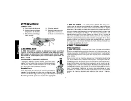
Français 16 INTRODUCTION COMPOSANTS A. Interrupteur à gâchette D. Poignée latérale B. Bouton de verrouillage E. Dispositif de protection en position de marche (Type 27, ouvert sous C. Bouton de verrouillage la meule ou l’accessoire) de la broche ASSEMBLAGE MISE EN GARDE : Arrêter et débrancher l’out...
Page 20 - MISE EN GARDE : Utiliser un dispositif de protection de type; Il est
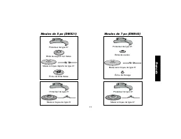
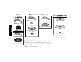
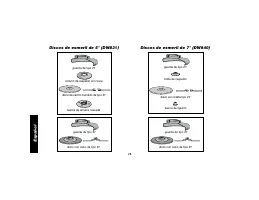
Français 18 Brosses métalliques circulaires Brosse forme coupelle de 3 po Meule métallique de 4 po Protecteur de type 27 Protecteur de type 27 Plateau porte-disque en caoutchouc Disque de ponçage Écrou de bride filetée Disques de ponçage (DW831) Disques souples de ponçage Protecteur de type 27 Disqu...
Page 21 - Le meulage et la coupe de bord ne doivent; Meulage avec Disques Abrasifs
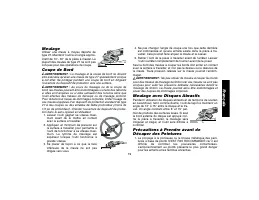
Français 19 Meulage Utiliser une meule à moyeu déporté detype 27. Maintenir l’outil à un angle approx-imatif de 10°- 30° de la pièce à meuler. Laplupart des meules de type 27 ne sont pasconçues pour des opérations de coupe. Coupe de Bord AVERTISSEMENT : Le meulage et la coupe de bord ne doivent être...
Page 22 - SÉCURITÉ PERSONNELLE; Débrancher l’outil avant d’installer ou de; FIXATION DU DISPOSITIF DE PROTECTION; Ne pas utiliser la meule si le dispositif de pro-
Français 20 2. Comme il est difficile de déterminer si une peinture contient du plomb sans en faire une analyse chimique, nous recommandonsles précautions suivantes au moment de poncer toute peinture : SÉCURITÉ PERSONNELLE 1. Les enfants et les femmes enceintes ne doivent pas entrer dans une zone de...
Page 23 - Ne pas resserrer la vis de réglage si le; RETRAIT DU DISPOSITIF DE PROTECTION; Ne pas resserrer la vis de réglage si le
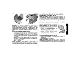
Français 21 REMARQUE : Le dispositif de protection est ajusté d’usine au diamètre du moyeu de la broche. Si le dispositif de protectionrequiert ajustement après une certaine période d’utilisation, fairetout réglage de la façon suivante. Avec le mécanisme de verrouil-lage en position fermé serrer ou ...
Page 24 - Un dispositif de protection adéquat doit être; Lubrification
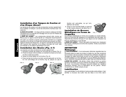
Français 22 Installation d’un Tampon de Soutien etd’un Disque Abrasif Les tampons de soutien sont des accessoires vendus séparément.Pour installer un tampon, suivre les instructions fournies avec l’ac-cessoire. MISE EN GARDE : Un dispositif de protection adéquat doit être réinstallé pour tout travau...
Page 25 - Réparations; CONTRAT D’ENTRETIEN GRATUIT D’UN AN
Français 23 l’utilisation. (Les outils utilisés constamment dans les travauxcontinus ou à service intense et ceux exposés à la chaleurnécessitent une lubrification plus fréquente.) Seuls les réparateursd’outils électriques compétents peuvent effectuer cette lubrification,comme le personnel des centr...
Page 26 - No ajustarse a las instrucciones; CONSERVE ESTAS INSTRUCCIONES; Mantenga el área de trabajo limpia y bien iluminada.
Español 24 Instrucciones de seguridad generales ¡ADVERTENCIA! Lea todas las instrucciones hastacomprenderlas. No ajustarse a las instrucciones siguientes puede ser causa de choque eléctrico, incendio olesiones graves. CONSERVE ESTAS INSTRUCCIONES ÁREA DE TRABAJO• Mantenga el área de trabajo limpia y...
Page 27 - Español; Calibre mínimo para cordones de extensión; Más
Español 25 Calibre mínimo para cordones de extensión Volts Longitud total del cordón en metros 120V 0-7,6 7,6-15,2 15,2-30,4 30,4-45,7 Amperaje Más No más Calibre del cordón AWG de de 12 - 16 14 12 No recomendado SEGURIDAD PERSONAL• Al utilizar una herramienta eléctrica, esté atento,concéntrese en l...
Page 28 - Utilice siempre la guarda apropiada con el disco de esmeril.
Español 26 • Utilice únicamente los accesorios recomendados por elfabricante para su modelo. Un mismo accesorio puede ser adecuado para una herramienta, pero peligroso si se usa en otra. SERVICIO• El servicio a la herramienta sólo debe realizarlo personalcualificado. El servicio o mantenimiento real...
Page 29 - PRECAUCIÓN: Preste una atención especial al esmerilado; INTRODUCCIÓN; COMPONENTES; A. Conmutador tipo gatillo
Español 27 • No opere esta herramienta durante períodos largos detiempo. La vibración causada por la acción de la herramienta puede ser dañina para sus manos y brazos. Use guantes paraun mejor amortiguamiento y descanse con frecuencia para lim-itar su exposición. ADVERTENCIA: Parte del polvo generad...
Page 31 - ATENCIÓN: Utilice una guarda de tipo 27 cuando use los; Los operadores y otras personas
Español 29 Discos de alambre cepillo de copa de alambre de 3" disco de alambre de 4" guarda de tipo 27 guarda de tipo 27 almohadilla de apoyo de caucho disco de lijado tuerca de amarre roscada Discos de lijado Discos lijadores de aletas guarda de tipo 27 disco lijador de aletas con cubo guar...
Page 32 - ATENCIÓN: Apague y desenchufe la herramienta antes de; Esmerilado
Español 30 Ensamblaje ATENCIÓN: Apague y desenchufe la herramienta antes de hacer ajustes de cualquier tipo o quitar o instalar accesorios.Antes de volver a conectar la herramienta, presione y suelte laparte posterior del conmutador para asegurar que la herra-mienta esté apagada. CONEXIÓN DEL MANGO ...
Page 33 - No use discos de esmerilado o corte de bordes; Lijado con Discos Abrasivos; SEGURIDAD PERSONAL
Español 31 1. Permita que la herramienta alcance su velocidad total antes de tocar la her-ramienta contra la superficie de trabajo. 2. Aplique presión mínima a la superficie de trabajo, permitiendo que la herramientaopere a alta velocidad. La velocidad deesmerilado es mayor cuando la her-ramienta fu...
Page 34 - SEGURIDAD AMBIENTAL; Desenchufe la herramienta antes de montar o quitar; CÓMO MONTAR LA GUARDA; No opere el esmeril con una guarda suelta o con el
Español 32 Los trabajadores deberán lavarse a fondo ANTES de comer,beber o fumar. No debe dejarse comida, bebida ni tabaco en lazona de trabajo, donde el polvo se podría posar sobre ellos. SEGURIDAD AMBIENTAL 1. La pintura debe eliminarse de forma que se reduzca al mínimo el polvo generado. 2. Las z...
Page 35 - CÓMO QUITAR LA GUARDA
Español 33 CÓMO QUITAR LA GUARDA 1. Abra el seguro de la guarda (A) y alinee la flecha de la guarda con la flecha del cárter. 2. Tire de la guarda hacia arriba hasta que sus orejetas enganchen y roten libremente en la ranura del cárter. 3. Con el seguro de la guarda abierto, gire la guarda hasta que...
Page 36 - Ajuste firmemente la brida roscada con la; Lubricación; Las herramientas D; Cepillos del motor; WALT Industrial
Español 34 3. Atornille la brida roscada al eje (Fig. 5).4. Gire el eje a mano mientras presiona el botón de bloqueo del eje (Fig. 6) hastaque el eje quede bloqueado, impidiendoque el eje rote. 5. Ajuste firmemente la brida roscada con la llave inglesa que viene incluida (Fig. 7). Cómo instalar Cepi...
Page 37 - La utilización de cualquier accesorio no; Reparaciones; AÑO DE SERVICIO GRATUITO
Español 35 provocar lesiones. La clasificación de los accesorios debe estarsiempre por encima de la velocidad de la herramienta, como semuestra en la placa de características de ésta. PRECAUCIÓN: La utilización de cualquier accesorio no recomendado para esta herramienta puede ser peligrosa. Reparaci...
Page 38 - Información Técnica; WALT mantendrá la herramienta y reemplazará las piezas gas-
Español 36 Información Técnica DW831 DW840 Tension de alimentación: 120 V AC 120 V AC Consumo de corriente: 12A 13A Frecuencia de operación: 50/60 Hz 50/60 Hz Potencia nominal: 1,339 W 1,450 W Rotación sin carga: 10 000/min 8 000/min D E WALT mantendrá la herramienta y reemplazará las piezas gas- ta...
Page 39 - The following are trademarks for one or more D
D E WALT Industrial Tool Co., 701 East Joppa Road, Baltimore, MD 21286 (OCT04) Form No. 392424-02 DW831, 840 Copyright © 2003, 2004 D E WALT The following are trademarks for one or more D E WALT power tools: the yellow and black color scheme; the “D” shaped air intake grill; the array of pyramids on...