Page 7 - Right; Left
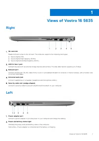
Views of Vostro 16 5635 Right 1. SD-card slot Reads from and writes to the SD card. The computer supports the following card types: ● Secure Digital (SD) ● Secure Digital High Capacity (SDHC) ● Secure Digital Extended Capacity (SDXC) 2. USB 3.2 Gen 1 port Connect devices such as external storage dev...
Page 8 - Top
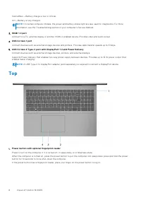
Solid amber—Battery charge is low or critical. Off—Battery is fully charged. NOTE: On certain computer models, the power and battery-status light are also used for diagnostics. For more information, see the Troubleshooting section in your computer’s Service Manual . 3. HDMI 1.4 port Connect to a TV,...
Page 9 - Front
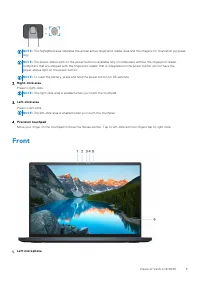
NOTE: The highlighted area indicates the actual active fingerprint reader area and the image is for illustration purposes only. NOTE: The power-status light on the power button is available only on computers without the fingerprint reader. Computers that are shipped with the fingerprint reader that ...
Page 10 - Bottom
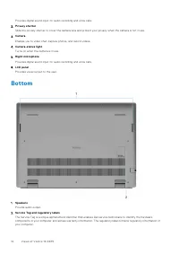
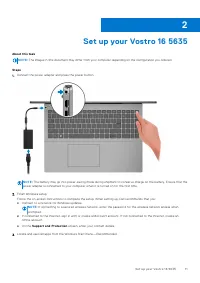
Provides digital sound input for audio recording and voice calls. 2. Privacy shutter Slide the privacy shutter to cover the camera lens and protect your privacy when the camera is not in use. 3. Camera Enables you to video chat, capture photos, and record videos. 4. Camera-status light Turns on when...
Page 13 - Dimensions and weight; Processor
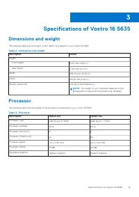
Specifications of Vostro 16 5635 Dimensions and weight The following table lists the height, width, depth, and weight of your Vostro 16 5635. Table 2. Dimensions and weight Description Values Height: Front height 15.67 mm (0.62 in.) Rear height 17.95 mm (0.71 in.) Width 356.78 mm (14.05 in.) Depth 2...
Page 14 - External ports
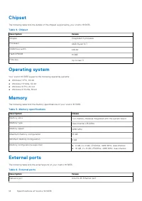
Chipset The following table lists the details of the chipset supported by your Vostro 16 5635. Table 4. Chipset Description Values Chipset Integrated in processor Processor AMD Ryzen 5/7 DRAM bus width 128-bit Flash EPROM 16 MB PCIe bus Up to Gen 3 Operating system Your Vostro 16 5635 supports the f...
Page 15 - Internal slots; Ethernet; Wireless module
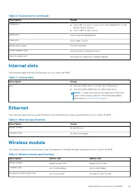
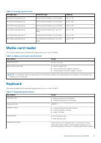
Table 6. External ports (continued) Description Values USB ports ● One USB 3.2 Gen 2 Type-C port with DisplayPort 1.4 AltMode/Power Delivery ● Two USB 3.2 Gen 1 ports Audio port One Universal headset jack Video port One HDMI 1.4 port Media-card reader One SD-card slot Power-adapter port One 4.50 mm ...
Page 16 - Audio; Storage
Table 9. Wireless module specifications (continued) Description Option one Option two Wireless standards ● WiFi 802.11a/b/g ● Wi-Fi 4 (WiFi 802.11n) ● Wi-Fi 5 (WiFi 802.11ac) ● Wi-Fi 6 (802.11ax) ● WiFi 802.11a/b/g ● Wi-Fi 4 (WiFi 802.11n) ● Wi-Fi 5 (WiFi 802.11ac) ● Wi-Fi 6E (802.11ax) Encryption ●...
Page 17 - Keyboard
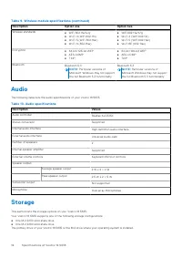
Table 11. Storage specifications Storage type Interface type Capacity M.2 2230 solid-state drive PCIe Gen3.0x4 NVMe, up to 32 Gbps Up to 1 TB M.2 2230 solid-state drive PCIe Gen4.0x4 NVMe, up to 64 Gbps Up to 1 TB M.2 2280 solid-state drive PCIe Gen4.0x4 NVMe, up to 64 Gbps Up to 2 TB M.2 2280 solid...
Page 18 - Keyboard shortcuts
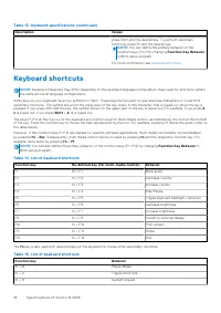
Table 13. Keyboard specifications (continued) Description Values press Shift and the desired key. To perform secondaryfunctions, press Fn and the desired key. NOTE: You can define the primary behavior of the function keys (F1–F12) changing Function Key Behavior in BIOS setup program. For more inform...
Page 19 - Camera; Touchpad
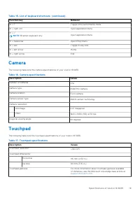
Table 15. List of keyboard shortcuts (continued) Function key Behavior fn + T Toggle Ultra performance mode fn + right ctrl Open application menu fn + / NOTE: Brazilian keyboard only Open application menu fn + Space bar Open Emoji menu fn + esc Toggle fn-key lock fn + left arrow Home fn + right arro...
Page 20 - Power adapter; Battery
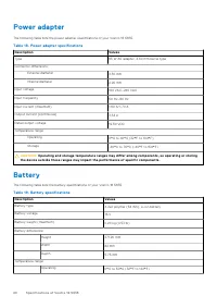
Power adapter The following table lists the power adapter specifications of your Vostro 16 5635. Table 18. Power adapter specifications Description Values Type 65 W AC adapter, 4.50 mm barrel type Connector dimensions: External diameter 4.50 mm Internal diameter 2.90 mm Input voltage 100 VAC–240 VAC...
Page 21 - Display
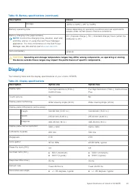
Table 19. Battery specifications (continued) Description Values Storage -20°C to 60°C (-4°F to 140°F) Battery operating time Varies depending on operating conditions and can significantlyreduce under certain power-intensive conditions. Battery charging time (approximate) NOTE: Control the charging t...
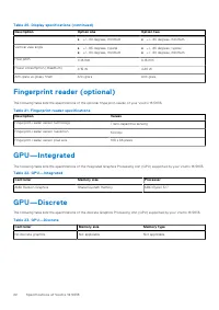
Page 22 - GPU—Integrated; GPU—Discrete
Table 20. Display specifications (continued) Description Option one Option two ● +/- 80 degrees, minimum ● +/- 80 degrees, minimum Vertical view angle ● +/- 85 degrees, typical ● +/- 80 degrees, minimum ● +/- 85 degrees, typical ● +/- 80 degrees, minimum Pixel pitch 0.18 mm 0.18 mm Power consumption...
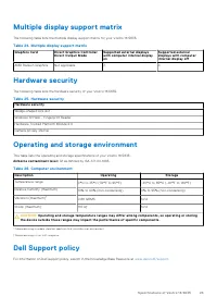
Page 23 - Multiple display support matrix; Hardware security; Operating and storage environment; Dell Support policy
Multiple display support matrix The following table lists the multiple display support matrix for your Vostro 16 5635. Table 24. Multiple display support matrix Graphics Card Direct Graphics Controller Direct Output Mode Supported external displays with computer internal display on Supported externa...
Page 24 - ComfortView; ComfortView Plus
ComfortView WARNING: Prolonged exposure to blue light from the display may lead to long-term effects such as eye strain, eye fatigue, or damage to the eyes. Blue light is a color in the light spectrum which has a short wavelength and high energy. Chronic exposure to blue light,particularly from digi...
Page 25 - Safety instructions; Before working inside your computer
Working inside your computer Safety instructions Use the following safety guidelines to protect your computer from potential damage and to ensure your personal safety. Unlessotherwise noted, each procedure included in this document assumes that you have read the safety information that shippedwith y...
Page 26 - Safety precautions; Standby power; Electrostatic discharge—ESD protection
NOTE: If you are using a different operating system, see the documentation of your operating system for shut-down instructions. 3. Disconnect your computer and all attached devices from their electrical outlets.4. Disconnect all attached network devices and peripherals, such as keyboard, mouse, and ...
Page 27 - ESD field service kit; Components of an ESD field service kit
The more difficult type of damage to recognize and troubleshoot is the intermittent (also called latent or "walking wounded")failure. Perform the following steps to prevent ESD damage: ● Use a wired ESD wrist strap that is properly grounded. The use of wireless anti-static straps is no longe...
Page 28 - ESD protection summary; Transporting sensitive components; BitLocker; Recommended tools
ESD protection summary It is recommended to use the traditional wired ESD grounding wrist strap and protective anti-static mat at all times whenservicing Dell products. In addition, it is critical to keep sensitive parts separate from all insulator parts while performing serviceand that they use ant...
Page 29 - Screw list
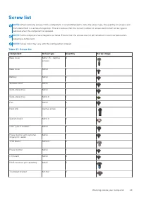
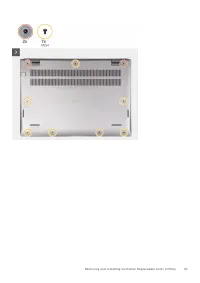
Screw list NOTE: When removing screws from a component, it is recommended to note the screw type, the quantity of screws, and then place them in a screw storage box. This is to ensure that the correct number of screws and correct screw type isrestored when the component is replaced. NOTE: Some compu...
Page 32 - Removing and installing Customer; Base cover; Removing the base cover
Removing and installing Customer Replaceable Units (CRUs) The replaceable components in this chapter are Customer Replaceable Units (CRUs). CAUTION: Customers can replace only the Customer Replaceable Units (CRUs) following the safety precautions and replacement procedures. NOTE: The images in this ...
Page 34 - Installing the base cover
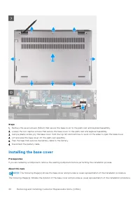
Steps 1. Remove the seven screws (M2x4) that secure the base cover to the palm-rest and keyboard assembly.2. Loosen the two captive screws that secure the base cover to the palm-rest and keyboard assembly.3. Using a plastic scribe, pry the base cover from the top left and continue to work on the sid...
Page 36 - Fan; Removing the fan; Installing the fan
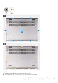
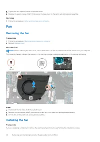
3. Tighten the two captive screws on the base cover.4. Replace the seven screws (M2x7) that secure the base cover to the palm-rest and keyboard assembly. Next steps 1. Follow the procedure in After working inside your computer . Fan Removing the fan Prerequisites 1. Follow the procedure in Before wo...
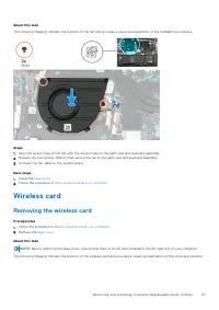
Page 37 - Wireless card; Removing the wireless card
About this task The following image(s) indicate the location of the fan and provides a visual representation of the installation procedure. Steps 1. Align the screw holes of the fan with the screw holes on the palm-rest and keyboard assembly.2. Replace the two screws (M2x3) that secure the fan to th...
Page 38 - Installing the wireless card
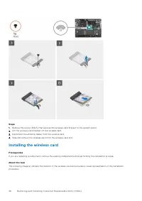
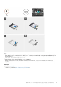
Steps 1. Remove the screw (M2x3) that secures the wireless-card bracket to the system board.2. Lift the wireless-card bracket off the wireless card.3. Disconnect the antenna cables from the wireless card.4. Slide and remove the wireless card from the wireless-card slot. Installing the wireless card ...
Page 40 - Installing the M.2 2230 solid-state drive
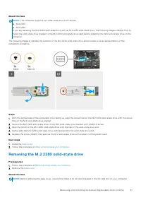
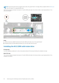
Solid-state drive Removing the M.2 2230 solid-state drive Prerequisites 1. Follow the procedure in Before working inside your computer . 2. Remove the base cover . About this task NOTE: Before removing the base cover, ensure that there is no SD card installed in the SD card slot on your computer. NO...
Page 42 - Installing the M.2 2280 solid-state drive
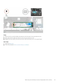
NOTE: Device Encryption will be triggered when either the system board or storage (SSD) is replaced. Refer to BitLocker for more information on suspending BitLocker The following image(s) indicate the location of the M.2 2280 solid-state drive and provides a visual representation of theremoval proce...
Page 44 - Removing and installing Field Replaceable; Lithium-ion battery precautions; Removing the battery
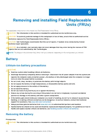
Removing and installing Field Replaceable Units (FRUs) The replaceable components in this chapter are Field Replaceable Units (FRUs). CAUTION: The information in this section is intended for authorized service technicians only. CAUTION: To avoid any potential damage to the component or loss of data,...
Page 45 - Installing the battery
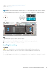
1. Follow the procedure in Before working inside your computer . 2. Remove the base cover . About this task NOTE: Before removing the base cover, ensure that there is no SD card installed in the SD card slot on your computer. The following image(s) indicate the location of the battery and provides a...
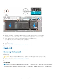
Page 46 - Heat sink; Removing the heat sink
Steps 1. Align the screw holes on the battery with the screw holes on the palm-rest and keyboard assembly.2. Replace the five screws (M2x3) that secure the battery to the palm-rest and keyboard assembly.3. Route the battery cable through the tabs and reconnect it to the system board.4. Adhere the ta...
Page 47 - Installing the heat sink
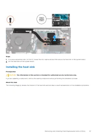
Steps 1. In reverse sequential order (4>3>2>1), loosen the four captive screws that secure the heat sink to the system board.2. Lift the heat sink off the system board. Installing the heat sink Prerequisites CAUTION: The information in this section is intended for authorized service technic...
Page 48 - Speaker; Removing the speakers
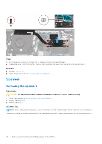
Steps 1. Align the captive screws on the heat sink to the screw holes on the system board.2. In sequential order (1>2>3>4), tighten the four captive screws that secure the heat sink to the system board. Next steps 1. Install the base cover . 2. Follow the procedure in After working inside y...
Page 49 - Installing the speakers
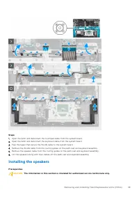
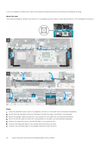
Steps 1. Open the latch and disconnect the touchpad cable from the system board.2. Open the latch and disconnect the keyboard cable from the system board.3. Peel the tapes that secure the WLAN cable to the system board.4. Remove the WLAN cable from the routing guides on the palm-rest and keyboard as...
Page 51 - Removing the coin-cell battery
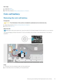
Next steps 1. Install the battery . 2. Install the base cover . 3. Follow the procedure in After working inside your computer . Coin-cell battery Removing the coin-cell battery Prerequisites CAUTION: The information in this section is intended for authorized service technicians only. 1. Follow the p...
Page 52 - Installing the coin-cell battery; Removing the I/O board
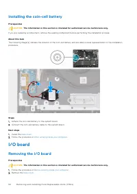
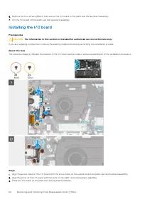
Installing the coin-cell battery Prerequisites CAUTION: The information in this section is intended for authorized service technicians only. If you are replacing a component, remove the existing component before performing the installation process. About this task The following image(s) indicate the...
Page 54 - Installing the I/O board
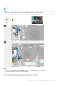
6. Remove the two screws (M2x3) that secure the I/O board to the palm-rest and keyboard assembly.7. Lift the I/O board off the palm-rest and keyboard assembly. Installing the I/O board Prerequisites CAUTION: The information in this section is intended for authorized service technicians only. If you ...
Page 55 - Removing the power button with optional fingerprint reader
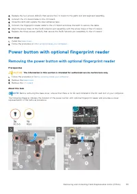
4. Replace the two screws (M2x3) that secure the I/O board to the palm-rest and keyboard assembly.5. Connect the I/O-board cable to the I/O board.6. Close the latch and replace the clear adhesive tape.7. Connect the fingerprint-reader cable to the I/O board and close the latch to secure the cable.8....
Page 56 - Installing the power button with optional fingerprint reader
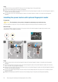
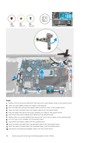
Steps 1. Remove the three screws (M2.5x5) that secure the left display hinge to the system board.2. Open the left display hinge at an angle of 90 degrees.3. Remove the screw (M2x3) that secures the power button with optional fingerprint reader with optional fingerprint reader to the palm-rest and ke...
Page 57 - Removing the power button
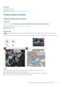
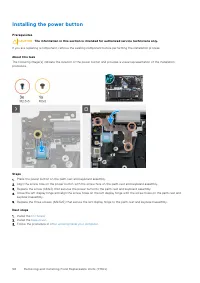
Next steps 1. Install the I/O board . 2. Install the base cover . 3. Follow the procedure in After working inside your computer . Power-button module Removing the power button Prerequisites CAUTION: The information in this section is intended for authorized service technicians only. 1. Follow the pr...
Page 58 - Installing the power button
Installing the power button Prerequisites CAUTION: The information in this section is intended for authorized service technicians only. If you are replacing a component, remove the existing component before performing the installation process. About this task The following image(s) indicate the loca...
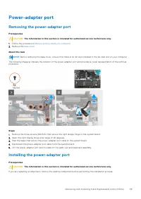
Page 59 - Removing the power-adapter port; Installing the power-adapter port
Power-adapter port Removing the power-adapter port Prerequisites CAUTION: The information in this section is intended for authorized service technicians only. 1. Follow the procedure in Before working inside your computer . 2. Remove the base cover . About this task NOTE: Before removing the base co...
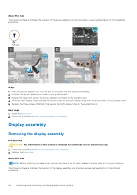
Page 60 - Display assembly; Removing the display assembly
About this task The following image(s) indicate the location of the power-adapter port and provides a visual representation of the installationprocedure. Steps 1. Place the power-adapter port into the slot on the palm-rest and keyboard assembly.2. Connect the power-adapter port cable to the system b...
Page 62 - Installing the display assembly
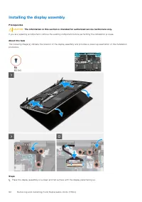
Installing the display assembly Prerequisites CAUTION: The information in this section is intended for authorized service technicians only. If you are replacing a component, remove the existing component before performing the installation process. About this task The following image(s) indicate the ...
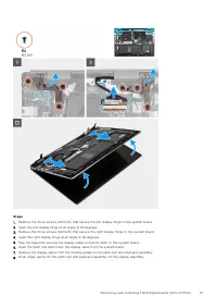
Page 63 - Trusted Platform Module; Removing the Trusted Platform Module (TPM) board
2. Gently place the palm-rest and keyboard assembly under the display hinges.3. Close the left display hinge and align the screw holes on the left display hinge with the screw holes on the palm-rest and keyboard assembly. 4. Replace the three screws (M2.5x5) that secure the left display hinge to the...
Page 64 - Installing the Trusted Platform Module (TPM) board
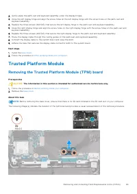
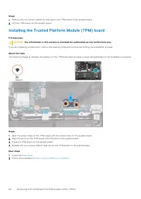
Steps 1. Remove the two screws (M2x3.5) that secure the TPM board to the system board.2. Lift the TPM board off the system board. Installing the Trusted Platform Module (TPM) board Prerequisites CAUTION: The information in this section is intended for authorized service technicians only. If you are ...
Page 65 - System board; Removing the system board
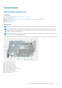
System board Removing the system board Prerequisites 1. Follow the procedure in Before working inside your computer . 2. Remove the base cover . 3. Remove the M.2 2230 solid-state drive or M.2 2280 solid-state drive , whichever applicable. 4. Remove the wireless card . 5. Remove the heat sink . Abou...
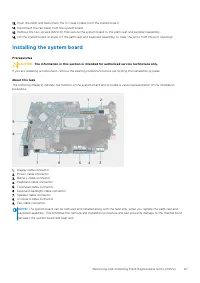
Page 67 - Installing the system board
13. Open the latch and disconnect the I/O board cable from the system board14. Disconnect the fan cable from the system board.15. Remove the two screws (M2x1.8) that secure the system board to the palm-rest and keyboard assembly.16. Lift the system board at angle off the palm-rest and keyboard assem...
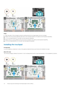
Page 69 - Removing the touchpad
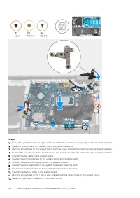
13. Replace the two screws (M2x4) that secure the Type-C port-bracket to the system board.14. Connect the power-adapter port cable to the system board.15. Adhere the tapes that secure the power-adapter port cable to the system board.16. Connect the display cable from the system board and close the l...
Page 70 - Installing the touchpad
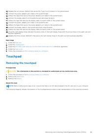
Steps 1. Open the latch of the touchpad connector and disconnect the touchpad cable from the touchpad.2. Remove the three screws (M1.6x2) that secure the touchpad bracket to the palm-rest and keyboard assembly.3. Lift the touchpad bracket off the palm-rest and keyboard assembly.4. Remove the two scr...
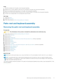
Page 71 - Palm-rest and keyboard assembly; Removing the palm-rest and keyboard assembly
Steps 1. Slide the touchpad onto the palm-rest and keyboard assembly.2. Replace the two screws (M2x1.8) that secure the touchpad to the palm-rest and keyboard assembly.3. Align the touchpad bracket and place it on the palm-rest and keyboard assembly.4. Replace the three screws (M1.6x2) that secure t...
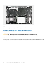
Page 72 - Installing the palm-rest and keyboard assembly
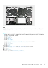
Steps After performing the pre-requisites, you are left with the palm-rest and keyboard assembly. Installing the palm-rest and keyboard assembly Prerequisites CAUTION: The information in this section is intended for authorized service technicians only. If you are replacing a component, remove the ex...
Page 74 - Operating system; Drivers and downloads
Software This chapter details the supported operating systems along with instructions on how to install the drivers. Operating system Your Vostro 16 5635 supports the following operating systems: ● Windows 11 Pro, 64-bit ● Windows 11 Home, 64-bit ● Windows 10 Pro, 64-bit ● Windows 10 Home, 64-bit Dr...
Page 75 - BIOS setup; Entering BIOS setup program; Navigation keys; One time boot menu
BIOS setup CAUTION: Unless you are an expert computer user, do not change the settings in the BIOS Setup program. Certain changes can make your computer work incorrectly. NOTE: Depending on the computer and its installed devices, the items listed in this section may or may not be displayed. NOTE: Be...
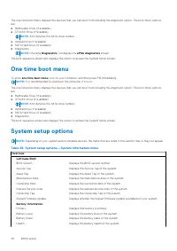
Page 76 - System setup options
The one-time boot menu displays the devices that you can boot from including the diagnostic option. The boot menu optionsare: ● Removable Drive (if available) ● STXXXX Drive (if available) NOTE: XXX denotes the SATA drive number. ● Optical Drive (if available) ● SATA Hard Drive (if available) ● Diag...
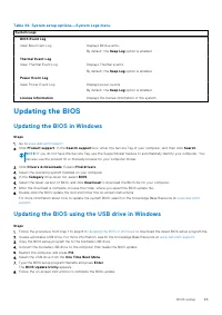
Page 85 - Updating the BIOS; Updating the BIOS using the USB drive in Windows
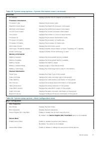
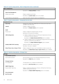
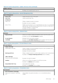
Table 44. System setup options—System Logs menu System Logs BIOS Event Log Clear Bios Event Log Displays BIOS events. By default, the Keep Log option is enabled. Thermal Event Log Clear Thermal Event Log Displays Thermal events. By default, the Keep Log option is enabled. Power Event Log Clear Power...
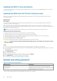
Page 86 - System and setup password
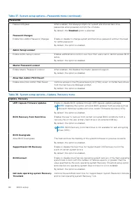
Updating the BIOS in Linux and Ubuntu To update the system BIOS on a computer that is installed with Linux or Ubuntu, see the knowledge base article 000131486 at www.dell.com/support . Updating the BIOS from the F12 One-Time boot menu Update your computer BIOS using the BIOS update.exe file that is ...
Page 88 - Clearing CMOS settings; Clearing BIOS (System Setup) and System passwords
Clearing CMOS settings About this task CAUTION: Clearing CMOS settings will reset the BIOS settings on your computer. Steps 1. Remove the base cover . 2. Disconnect the battery cable from the system board.3. Remove the coin-cell battery . 4. Wait for one minute.5. Replace the coin-cell battery . 6. ...
Page 90 - Running the SupportAssist Pre-Boot System Performance Check
Dell SupportAssist Pre-boot System PerformanceCheck diagnostics About this task SupportAssist diagnostics (also known as system diagnostics) performs a complete check of your hardware. The DellSupportAssist Pre-boot System Performance Check diagnostics is embedded with the BIOS and is launched by th...
Page 91 - How to invoke LCD BIST Test
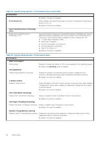
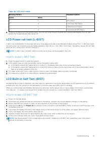
Table 46. LED error codes Blinking Pattern Possible Problem Amber White 2 1 CPU Failure 2 8 LCD Power Rail Failure 1 1 TPM Detection Failure 2 4 Unrecoverable SPI Failure 4. If there is no failure with the system board, the LCD will cycle through the solid color screens described in the LCD-BIST sec...
Page 92 - System-diagnostic lights; Recovering the operating system
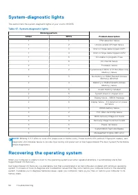
System-diagnostic lights This section lists the system-diagnostic lights of your Vostro 16 5635. Table 47. System-diagnostic lights Blinking pattern Problem description Amber White 1 1 TPM detection failure 1 2 Unrecoverable SPI flash failure 1 3 Short in hinge cable tripped OCP1 1 4 Short in hinge ...
Page 93 - Backup media and recovery options; WiFi power cycle
You can also download it from the Dell Support website to troubleshoot and fix your computer when it fails to boot into theirprimary operating system due to software or hardware failures. For more information about the Dell SupportAssist OS Recovery, see Dell SupportAssist OS Recovery User's Guide a...
Page 95 - Contacting Dell
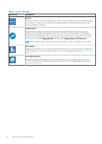
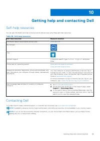
Getting help and contacting Dell Self-help resources You can get information and help on Dell products and services using these self-help resources: Table 48. Self-help resources Self-help resources Resource location Information about Dell products and services www.dell.com My Dell app Tips Contact ...