Page 6 - Right; Left
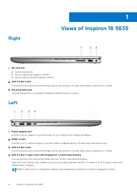
Views of Inspiron 16 5635 Right 1. SD-card slot ● Secure Digital (SD) ● Secure Digital High Capacity (SDHC) ● Secure Digital Extended Capacity (SDXC) 2. USB 3.2 Gen 1 port Connect devices such as external storage devices and printers. Provides data transfer speeds up to 5 Gbps. 3. Universal audio ja...
Page 7 - Top
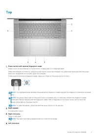
Top 1. Power button with optional fingerprint reader Press to turn on the computer if it is turned off, in sleep state, or in hibernate state. When the computer is turned on, press the power button to put the computer into sleep state; press and hold the powerbutton for 10 seconds to force shut-down...
Page 8 - Front
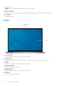
Press to left-click. NOTE: The left-click area is enabled when you touch the touchpad. 5. Precision touchpad Move your finger on the touchpad to move the mouse pointer. Tap to left-click and two fingers tap to right-click. 6. Left speaker Provides audio output. Front 1. Left microphone Provides digi...
Page 9 - Bottom
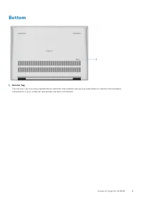
Bottom 1. Service Tag The Service Tag is a unique alphanumeric identifier that enables Dell service technicians to identify the hardwarecomponents in your computer and access warranty information. Views of Inspiron 16 5635 9
Page 12 - Dimensions and weight; Processor
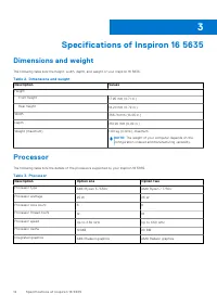
Specifications of Inspiron 16 5635 Dimensions and weight The following table lists the height, width, depth, and weight of your Inspiron 16 5635. Table 2. Dimensions and weight Description Values Height: Front height 17.95 mm (0.71 in.) Rear height 18.20 mm (0.72 in.) Width 356.78 mm (14.05 in.) Dep...
Page 13 - External ports
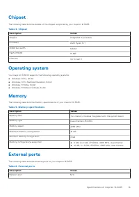
Chipset The following table lists the details of the chipset supported by your Inspiron 16 5635. Table 4. Chipset Description Values Chipset Integrated in processor Processor AMD Ryzen 5/7 DRAM bus width 128-bit Flash EPROM 16 MB PCIe bus Up to Gen 3 Operating system Your Inspiron 16 5635 supports t...
Page 14 - Internal slots; Wireless module
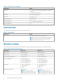
Table 6. External ports (continued) Description Values USB ports ● One USB 3.2 Gen 2 port with DisplayPort™ and PowerDelivery ● Two USB 3.2 Gen 1 ports Audio port One Universal headset jack Video port One HDMI 1.4 port Media-card reader One SD-card slot Power-adapter port ● One 4.50 mm x 2.90 mm DC-...
Page 15 - Audio; Storage
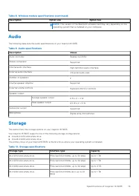
Table 8. Wireless module specifications (continued) Description Option one Option two NOTE: The version of the Bluetooth wireless card may vary depending on the operating system that is installed on your computer. Audio The following table lists the audio specifications of your Inspiron 16 5635. Tab...
Page 16 - Keyboard
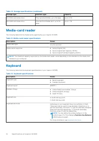
Table 10. Storage specifications (continued) Storage type Interface type Capacity M.2 2280 solid-state drive PCIe Gen4.0x4 NVMe, up to 64 Gbps Up to 2 TB M.2 2280 solid-state drive PCIe Gen3.0x4 NVMe QLC, up to 32Gbps Up to 1 TB Media-card reader The following table lists the media cards supported b...
Page 18 - Camera; Touchpad; Power adapter
Table 14. List of keyboard shortcuts (continued) Function key Behavior fn + right arrow End Camera The following table lists the camera specifications of your Inspiron 16 5635. Table 15. Camera specifications Description Values Number of cameras One Camera type RGB FHD Camera Camera location Front c...
Page 19 - Battery
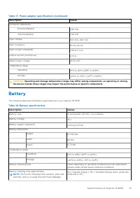
Table 17. Power adapter specifications (continued) Description Values Connector dimensions: External diameter 4.50 mm Internal diameter 2.90 mm Input voltage 100 VAC–240 VAC Input frequency 50 Hz–60 Hz Input current (maximum) 1.60 A/1.70 A Output current (continuous) 3.34 A Rated output voltage 19.5...
Page 20 - Display
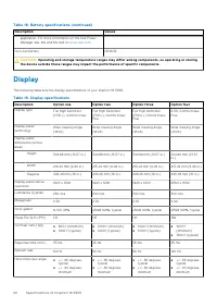
Table 18. Battery specifications (continued) Description Values application. For more information on the Dell PowerManager see, Me and My Dell on www.dell.com . Coin-cell battery CR2032 CAUTION: Operating and storage temperature ranges may differ among components, so operating or storing the device ...
Page 21 - GPU—Integrated
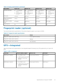
Table 19. Display specifications (continued) Description Option one Option two Option three Option four Vertical view angle ● +/- 85 degrees,typical ● +/- 80 degrees,minimum ● +/- 85 degrees,typical ● +/- 80 degrees,minimum ● +/- 85 degrees,typical ● +/- 80 degrees,minimum ● +/- 85 degrees,typical ●...
Page 22 - GPU—Discrete; Multiple display support matrix; Operating and storage environment; Dell Support policy
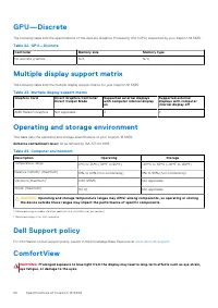
GPU—Discrete The following table lists the specifications of the discrete Graphics Processing Unit (GPU) supported by your Inspiron 16 5635. Table 22. GPU—Discrete Controller Memory size Memory type No discrete graphics N/A N/A Multiple display support matrix The following table lists the multiple d...
Page 23 - ComfortView Plus
Blue light is a color in the light spectrum which has a short wavelength and high energy. Chronic exposure to blue light,particularly from digital sources, may disrupt sleep patterns and cause long-term effects such as eye strain, eye fatigue, ordamage to the eyes. ComfortView mode can be enabled an...
Page 24 - Safety instructions; Before working inside your computer
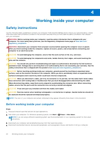
Working inside your computer Safety instructions Use the following safety guidelines to protect your computer from potential damage and to ensure your personal safety. Unlessotherwise noted, each procedure included in this document assumes that you have read the safety information that shippedwith y...
Page 25 - Safety precautions; Standby power; Electrostatic discharge—ESD protection
5. Remove any media card and optical disk from your computer, if applicable.6. Enter the service mode, if you are able to power on your computer. Service Mode Service Mode is used to cut-off power, without disconnecting battery cable from system board prior conducting repairs inthe computer. CAUTION...
Page 26 - ESD field service kit; Components of an ESD field service kit
Due to the increased density of semiconductors used in recent Dell products, the sensitivity to static damage is now higher thanin previous Dell products. For this reason, some previously approved methods of handling parts are no longer applicable. Two recognized types of ESD damage are catastrophic...
Page 27 - ESD protection summary; Transporting sensitive components; BitLocker; Recommended tools
● ESD Packaging – All ESD-sensitive devices must be shipped and received in static-safe packaging. Metal, static-shielded bags are preferred. However, you should always return the damaged part using the same ESD bag and packaging that thenew part arrived in. The ESD bag should be folded over and tap...
Page 28 - Screw list
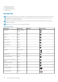
● Phillips screwdriver #0 ● Phillips screwdriver #1 ● Torx #5 (T5) screwdriver ● Plastic scribe Screw list NOTE: When removing screws from a component, it is recommended to note the screw type, the quantity of screws, and then place them in a screw storage box. This is to ensure that the correct num...
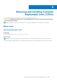
Page 31 - Removing and installing Customer; Base cover; Removing the base cover
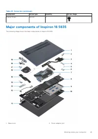
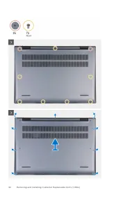
Removing and installing Customer Replaceable Units (CRUs) The replaceable components in this chapter are Customer Replaceable Units (CRUs). CAUTION: Customers can replace only the Customer Replaceable Units (CRUs) following the safety precautions and replacement procedures. NOTE: The images in this ...
Page 33 - Installing the base cover
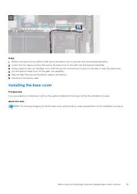
Steps 1. Remove the seven screws (M2x4) that secure the base cover to the palm-rest and keyboard assembly.2. Loosen the two captive screws that secure the base cover to the palm-rest and keyboard assembly.3. Using a plastic scribe, pry the base cover from the top left and continue to work on the sid...
Page 35 - Wireless card; Removing the wireless card
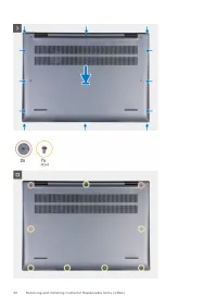
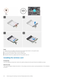
Steps 1. Ensure the battery cable has been connected to the system board.2. Place and snap the base cover into place on the palm-rest and keyboard assembly.3. Tighten the two captive screws on the base cover.4. Replace the seven screws (M2x4) to secure the base cover to the palm-rest and keyboard as...
Page 36 - Installing the wireless card
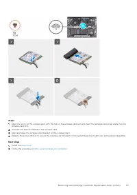
Steps 1. Remove the screw (M2x3) that secures the wireless-card bracket to the system board.2. Lift the wireless-card bracket off the wireless card.3. Disconnect the antenna cables from the wireless card.4. Slide and remove the wireless card from the wireless-card slot. Installing the wireless card ...
Page 39 - Installing the M.2 2230 solid-state drive
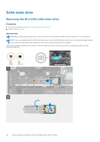
Steps 1. Remove the M2x3 screw that secures the M.2 2230 solid-state drive with bracket from the solid-state drive slot.2. Slide the M.2 2230 solid-state drive with bracket from the peg and lift it from the system board.3. Remove the M2x1.8 screw that secures the M.2 2230 solid-state drive to the M....
Page 41 - Installing the M.2 2280 solid-state drive
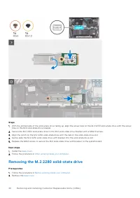
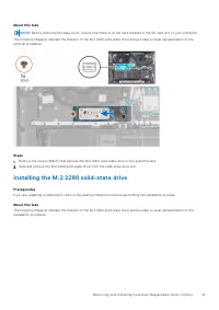
About this task NOTE: Before removing the base cover, ensure that there is no SD card installed in the SD card slot on your computer. The following image(s) indicate the location of the M.2 2280 solid-state drive and provides a visual representation of theremoval procedure. Steps 1. Remove the screw...
Page 42 - Fan; Removing the fan
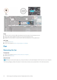
Steps 1. Align the notch on the M.2 2280 solid-state drive with the tab on the solid-state drive slot.2. Gently slide the M.2 2280 solid-state drive into the solid-state drive slot.3. Replace the screw (M2x3) to secure the M.2 2280 solid-state drive to the system board. Next steps 1. Install the bas...
Page 43 - Installing the fan
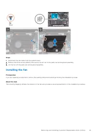
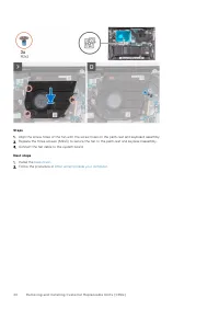
Steps 1. Disconnect the fan cable from the system board.2. Remove the three screws (M2x3) that secure the left fan to the palm-rest and keyboard assembly.3. Lift the fan off the palm-rest and keyboard assembly. Installing the fan Prerequisites If you are replacing a component, remove the existing co...
Page 45 - Removing and installing Field Replaceable; Rechargeable Li-ion battery precautions; Removing the battery
Removing and installing Field Replaceable Units (FRUs) The replaceable components in this chapter are Field Replaceable Units (FRUs). CAUTION: The information in this section is intended for authorized service technicians only. CAUTION: To avoid any potential damage to the component or loss of data,...
Page 46 - Installing the battery
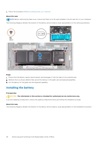
1. Follow the procedure in Before working inside your computer . About this task NOTE: Before removing the base cover, ensure that there is no SD card installed in the SD card slot on your computer. The following image(s) indicate the location of the battery and provides a visual representation of t...
Page 47 - Heat sink; Removing the heat sink
Steps 1. Align the screw holes on the battery with the screw holes on the palm-rest and keyboard assembly.2. Replace the five screws (M2x4) to secure the battery to the palm-rest and keyboard assembly.3. Route the battery cable through the tabs and reconnect it to the system board.4. Adhere the tape...
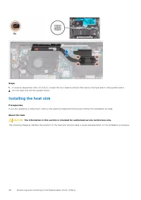
Page 48 - Installing the heat sink
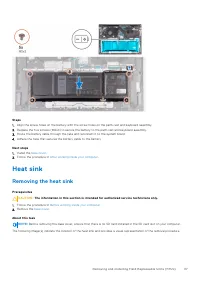
Steps 1. In reverse sequential order (4>3>2>1), loosen the four captive screws that secure the heat sink to the system board.2. Lift the heat sink off the system board. Installing the heat sink Prerequisites If you are replacing a component, remove the existing component before performing t...
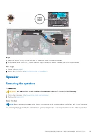
Page 49 - Speaker; Removing the speakers
Steps 1. Align the captive screws on the heat sink to the screw holes on the system board.2. In sequential order (1>2>3>4), tighten the four captive screws to secure the heat sink to the system board. Next steps 1. Install the base cover . 2. Follow the procedure in After working inside you...
Page 51 - Installing the speakers
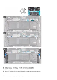
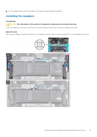
5. Lift the speakers along with their cables off the palm-rest and keyboard assembly. Installing the speakers Prerequisites CAUTION: The information in this section is intended for authorized service technicians only. If you are replacing a component, remove the existing component before performing ...
Page 52 - Removing the coin-cell battery
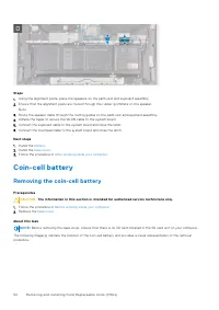
Steps 1. Using the alignment posts, place the speakers on the palm-rest and keyboard assembly.2. Ensure that the alignment posts are routed through the rubber grommets on the speaker. Note 3. Route the speaker cable through the routing guides on the palm-rest and keyboard assembly.4. Adhere the tape...
Page 53 - Installing the coin-cell battery
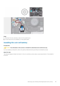
Steps 1. Disconnect the coin-cell battery cable from the system board.2. Lift and remove the coin-cell battery off the system board. Installing the coin-cell battery Prerequisites CAUTION: The information in this section is intended for authorized service technicians only. If you are replacing a com...
Page 54 - Removing the I/O board
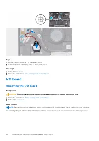
Steps 1. Adhere the coin-cell battery to the system board.2. Connect the coin-cell battery cable to the system board. Next steps 1. Install the base cover . 2. Follow the procedure in After working inside your computer . I/O board Removing the I/O board Prerequisites CAUTION: The information in this...
Page 55 - Installing the I/O board
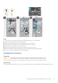
Steps 1. Remove the two screws (M2.5x5) that secure the left display hinge to the system board.2. Open the left display hinge at an angle of 90 degrees.3. Peel the tape that secures the I/O-board cable connector to the I/O board.4. Open the latch and disconnect the I/O-board cable cable from the I/O...
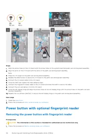
Page 56 - Removing the power button with fingerprint reader
Steps 1. Align the screw holes on the I/O board with the screw holes on the system board and palm-rest and keyboard assembly.2. Align the ports on the I/O board with the slots on the palm-rest and keyboard assembly. Note 3. Place the I/O board on the palm-rest and keyboard assembly.4. Replace the M2...
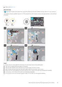
Page 58 - Installing the power button with fingerprint reader
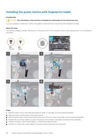
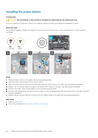
Installing the power button with fingerprint reader Prerequisites CAUTION: The information in this section is intended for authorized service technicians only. If you are replacing a component, remove the existing component before performing the installation process. About this task The following im...
Page 59 - Power button; Removing the power button
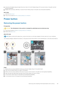
7. Close the left display hinge and align the screw holes on the left display hinge with the screw holes on the palm-rest and keyboard assembly. 8. Replace the two screws (M2.5x5) to secure the left display hinge to the palm-rest and keyboard assembly. Next steps 1. Install the base cover . 2. Follo...
Page 60 - Installing the power button
Installing the power button Prerequisites CAUTION: The information in this section is intended for authorized service technicians only. If you are replacing a component, remove the existing component before performing the installation process. About this task The following image(s) indicate the loca...
Page 61 - Removing the power-adapter port; Installing the power-adapter port
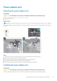
Power-adapter port Removing the power-adapter port Prerequisites CAUTION: The information in this section is intended for authorized service technicians only. 1. Follow the procedure in Before working inside your computer . 2. Remove the base cover . About this task NOTE: Before removing the base co...
Page 62 - Display assembly; Removing the display assembly
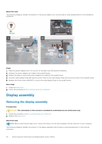
About this task The following image(s) indicate the location of the power-adapter port and provides a visual representation of the installationprocedure. Steps 1. Place the power-adapter port into the slot on the palm-rest and keyboard assembly.2. Connect the power-adapter port cable to the system b...
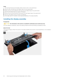
Page 64 - Installing the display assembly
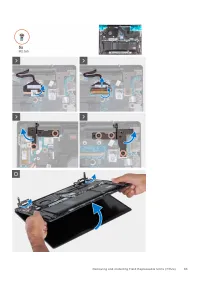
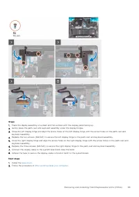
Steps 1. Peel the tape that secures the display-cable connector latch to the system board.2. Open the latch and disconnect the display cable from the system board.3. Remove the two screws (M2.5x5) that secure the left display hinge to the system board.4. Open the left display hinge at an angle of 90...
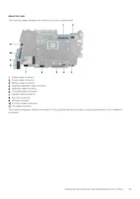
Page 66 - System board; Removing the system board
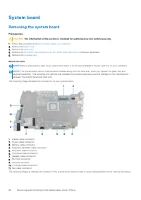
System board Removing the system board Prerequisites CAUTION: The information in this section is intended for authorized service technicians only. 1. Follow the procedure in Before working inside your computer . 2. Remove the base cover . 3. Remove the heat sink . 4. Remove the M.2 2230 solid-state ...
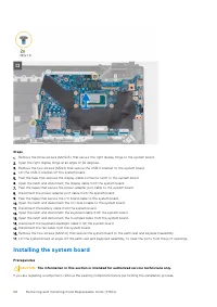
Page 68 - Installing the system board
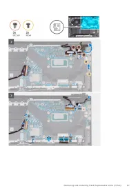
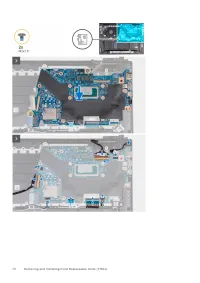
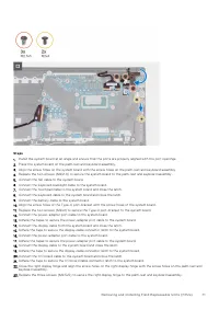
Steps 1. Remove the three screws (M2.5x5) that secure the right display hinge to the system board.2. Open the right display hinge at an angle of 90 degrees.3. Remove the two screws (M2x4) that secure the USB-C bracket to the system board.4. Lift the USB-C bracket off the system board.5. Peel the tap...
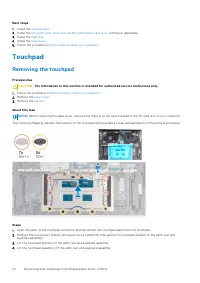
Page 72 - Removing the touchpad
Next steps 1. Install the wireless card . 2. Install the M.2 2230 solid-state drive or M.2 2280 solid-state drive , whichever applicable. 3. Install the heat sink . 4. Install the base cover . 5. Follow the procedure in After working inside your computer . Touchpad Removing the touchpad Prerequisite...
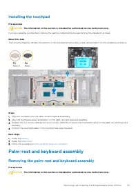
Page 73 - Installing the touchpad; Palm-rest and keyboard assembly; Removing the palm-rest and keyboard assembly
Installing the touchpad Prerequisites CAUTION: The information in this section is intended for authorized service technicians only. If you are replacing a component, remove the existing component before performing the installation process. About this task The following image(s) indicate the location...
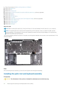
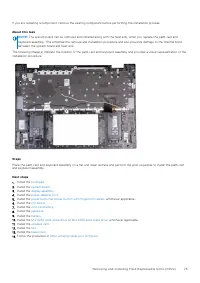
Page 74 - Installing the palm-rest and keyboard assembly
1. Follow the procedure in Before working inside your computer . 2. Remove the base cover . 3. Remove the fan . 4. Remove the wireless card . 5. Remove the M.2 2230 solid-state drive or M.2 2280 solid-state drive , whichever applicable. 6. Remove the battery . 7. Remove the speakers . 8. Remove the ...
Page 76 - Operating system; Drivers and downloads
Software This chapter details the supported operating systems along with instructions on how to install the drivers. Operating system Your Inspiron 16 5635 supports the following operating systems: ● Windows 11 Pro, 64-bit ● Windows 11 Pro National Education, 64-bit ● Windows 11 Home, 64-bit ● Windo...
Page 77 - BIOS setup; Entering BIOS setup program; Navigation keys; One time boot menu
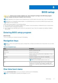
BIOS setup CAUTION: Unless you are an expert computer user, do not change the settings in the BIOS Setup program. Certain changes can make your computer work incorrectly. NOTE: Depending on the computer and its installed devices, the items listed in this section may or may not be displayed. NOTE: Be...
Page 78 - System setup options
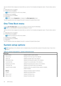
The one-time boot menu displays the devices that you can boot from including the diagnostic option. The boot menu optionsare: ● Removable Drive (if available) ● STXXXX Drive (if available) NOTE: XXX denotes the SATA drive number. ● Optical Drive (if available) ● SATA Hard Drive (if available) ● Diag...
Page 82 - Updating the BIOS; Updating the BIOS in Windows
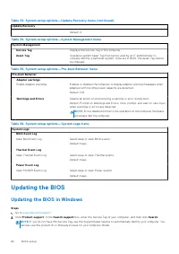
Table 33. System setup options—Update,Recovery menu (continued) Update,Recovery Default: 2. Table 34. System setup options—System Management menu System Management Service Tag Displays the Service Tag of the computer. Asset Tag Creates a system Asset Tag that can be used by an IT administrator touni...
Page 83 - Updating the BIOS using the USB drive in Windows; Updating the BIOS from the F12 One Time Boot menu
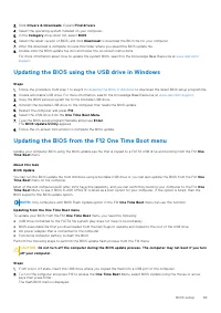
3. Click Drivers & Downloads . Expand Find drivers . 4. Select the operating system installed on your computer.5. In the Category drop-down list, select BIOS . 6. Select the latest version of BIOS, and click Download to download the BIOS file for your computer. 7. After the download is complete,...
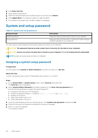
Page 84 - System and setup password; Assigning a system setup password
3. Click Flash from file . 4. Select external USB device.5. Select the file and double-click the flash target file, and then click Submit . 6. Click Update BIOS . The computer restarts to flash the BIOS. 7. The computer will restart after the BIOS update is completed. System and setup password Table...
Page 85 - Deleting or changing an existing system setup password; Clearing CMOS settings; Clearing BIOS (System Setup) and System passwords
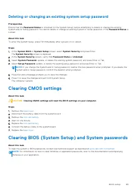
Deleting or changing an existing system setup password Prerequisites Ensure that the Password Status is Unlocked (in the System Setup) before attempting to delete or change the existing System and/or Setup password. You cannot delete or change an existing System or Setup password, if the Password St...
Page 87 - Running the SupportAssist Pre-Boot System Performance Check
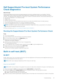
Dell SupportAssist Pre-boot System PerformanceCheck diagnostics About this task SupportAssist diagnostics (also known as system diagnostics) performs a complete check of your hardware. The DellSupportAssist Pre-boot System Performance Check diagnostics is embedded with the BIOS and is launched by th...
Page 88 - How to invoke LCD BIST Test
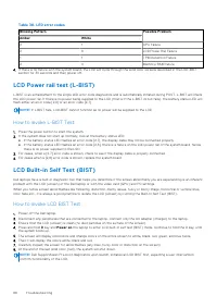
Table 38. LED error codes Blinking Pattern Possible Problem Amber White 2 1 CPU Failure 2 8 LCD Power Rail Failure 1 1 TPM Detection Failure 2 4 Memory/RAM failure 4. If there is no failure with the system board, the LCD will cycle through the solid color screens described in the LCD-BIST section fo...
Page 89 - System-diagnostic lights; Recovering the operating system
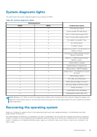
System-diagnostic lights This section lists the system-diagnostic lights of your Inspiron 16 5635. Table 39. System-diagnostic lights Blinking pattern Problem description Amber White 1 1 TPM detection failure 1 2 Unrecoverable SPI flash failure 1 3 Short in hinge cable tripped OCP1 1 4 Short in hing...
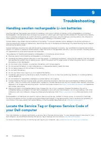
Page 90 - Backup media and recovery options; Drain residual flea power (perform hard reset)
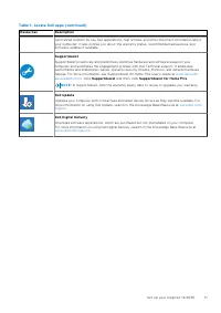
You can also download it from the Dell Support website to troubleshoot and fix your computer when it fails to boot into theirprimary operating system due to software or hardware failures. For more information about the Dell SupportAssist OS Recovery, see Dell SupportAssist OS Recovery User's Guide a...
Page 92 - Contacting Dell
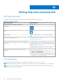
Getting help and contacting Dell Self-help resources You can get information and help on Dell products and services using these self-help resources: Table 40. Self-help resources Self-help resources Resource location Information about Dell products and services www.dell.com My Dell app Tips Contact ...