Dell PowerConnect J-EX4200 - Quick Guide
Dell PowerConnect J-EX4200 – Quick Guide, read for free online in PDF format. We hope this helps you resolve any issues you may have. If you have further questions, please contact us through the contact form.

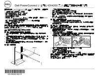




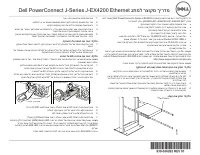
Table of Contents:
- Page 2 – Safety Warnings Summary
- Page 3 – 管理型號為; 孬憘㓧㩅; 春⸩㬎
- Page 4 – Juniper Networks; 產品編號:; 安全警告摘要; Dell Inc; 聯絡。
- Page 5 – 规范型号为; ⸘孔㓧㩅; 析⸩㧕
- Page 6 – 产品编号:; 安全警告汇总
- Page 7 – Ce comportement est normal.; XSSRUWGHPRQWDJH; Clip de fixation
- Page 8 – Récapitulatif des messages de sécurité
- Page 9 – Feststellhebel
- Page 10 – Zusammenfassung der Sicherheitsinformationen
- Page 11 – Perilaku ini; Klip penahan
- Page 12 – Ringkasan Peringatan Keselamatan
- Page 13 – 規定モデル番号; ขࠅઃߌࡉࠤ࠶࠻
- Page 14 – パーツ番号; 安全上の注意の要約
- Page 15 – 㣙㵝; Ḕ㥉
- Page 16 – 부품; 안전
- Page 17 – Esse comportamento é normal.; WRQTVGFGOQPVCIGO; Clipe de retenção
- Page 18 – Resumo dos avisos de segurança
- Page 19 – Este comportamiento es normal.; RSRUWHGHPRQWDMH; Clip de retención
- Page 20 – Resumen de advertencias de seguridad
- Page 21 – model denetim; XWWXUPDN ̧ġHEHQWL; XWXFXNóVND
- Page 22 – “root”
- Page 23 – םגד ירפסמ; Mounting rack
- Page 24 – טסוגואב; תינושאר הרוצת תרדגה עצב :; MAINTENANCE MENU; Out-of-band Management—Configure management port; תוחיטבה תורהזא תיצמת
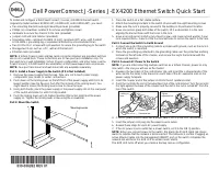
Dell PowerConnect J-Series J-EX4200 Ethernet Switch Quick Start
To install and configure a Dell PowerConnect J-Series J-EX4200 Ethernet Switch
(
regulatory model numbers EX4200-24T, EX4200-24F, and EX4200-48T
), you need:
z
Two mounting brackets and eight mounting screws (provided)
z
Phillips (+) screwdriver number 2 to remove and tighten screws
z
Hardware to secure the chassis to the rack (provided)
z
Jumper cord and cord retainer (provided)
z
Grounding cable—minimum 14 AWG (2 mm²), minimum 90°C wire—with Panduit
LCD6-14BH-L grounding lug or equivalent attached by a licensed electrician
z
Two 10-32x.25-in. screws with split washers to secure the grounding lug to the switch
z
Management host, such as a PC, with an Ethernet port
z
Ethernet cable (provided)
NOTE:
A Virtual Chassis cable and two cable connector retainers are provided, but their
use is not covered here. These instructions are for two-post rack installation only. For
four-post rack or wall installation, Virtual Chassis configuration, and other tasks, see the
PowerConnect J-EX4200 switch documentation at
http://www/support.dell.com/manuals
.
NOTE:
Four-post rack-mount and wall-mount kits are available separately.
Part 1: Install a Power Supply in the Switch (If It Is Not Installed)
1. Remove the power supply from the bag. Take care not to touch power supply
components, pins, leads, or solder connections.
2. Push down on the locking lever on the left front of the power supply until it is in its
lowest position (see the figure in Part 4 for the location of the locking lever). You
might need to loosen the locking lever screw to move the lever.
3. Using both hands, place the power supply in the power supply slot on the rear panel
of the switch and slide it in until it is fully seated.
4. Push the locking lever up to its highest position (this action might pull the power
supply in). Tighten the locking lever screw using the screwdriver.
Part 2: Mount the Switch
1. Place the switch on a flat, stable surface.
2. Attach the mounting brackets to the switch chassis with the eight mounting screws.
3. Make sure the rack is properly secured to the building in its permanent location.
4. Have one person grasp both sides of the switch, lift it, and position it in the rack,
aligning the bracket holes with the holes in the rack.
5. Have a second person install a rack-mount screw—and cage nut and washer if your
rack requires them—in each of the four bracket holes to secure the switch to the rack.
Part 3: Connect the Switch to Earth Ground
1. Connect one end of the grounding cable to a proper earth ground, such as the rack in
which the switch is mounted.
2. Place the grounding lug attached to the grounding cable over the protective earthing
terminal on the left side of the chassis, and secure the lug to the terminal with the
screws and washers.
Part 4: Connect AC Power to the Switch
NOTE:
If you are interconnecting multiple switches as a Virtual Chassis, power on only
one switch—the one you will use as the master.
1. Squeeze the two sides of the cord retainer clip, and insert the L-shaped ends of the
wire clip into the holes in the bracket on each side of the AC appliance inlet on the
power supply faceplate.
2. Insert the coupler end of the jumper cord into the AC appliance inlet.
3. Push the cord into the slot in the adjustment nut of the cord retainer. Turn the nut until
it is tight against the base of the coupler and the slot in the nut is turned 90° from the
top of the switch.
4. If the AC power source outlet has a power switch, set it to the OFF (0) position.
5. Insert the jumper cord plug into the power source outlet.
6. Repeat these steps for each AC power supply.
7. If the AC power source outlet has a power switch, set it to the ON (|) position.
NOTE:
When you connect power to the switch, the Alarm (ALM) LED lights red (major
alarm) to indicate that the network is disconnected.
This behavior is normal.
Plugging an
active Ethernet cable into the management (MGMT) port on the switch completes the
network link and turns the ALM LED to amber (minor alarm).
The ALM LED turns off when you create a backup rescue configuration.
G
-OUNTINGBRACKET
G
-OUNTINGBRACKET
AC
DC
Locking
lever
Tighten
adjustment nut.
Retainer clip
Adjustment nut
AC
DC
g020063
"Loading the manual" means you need to wait until the file loads and becomes available for online reading. Some manuals are very large, and the time they take to appear depends on your internet speed.
Was this manual helpful?
About this manual
- Brand
- Dell
- Model
- PowerConnect J-EX4200
- Document type
- Quick Guide
- Language(s)
- English
- Pages
- 24
- File size
- 3.2 MB
- Format
Summary
Information in this document is subject to change without notice. Trademarks used in this text: Dell ™ , the DELL™ logo, and PowerConnect™ are trademarks of Dell Inc. Juniper Networks® and Junos® are registered trademarks of Juniper Networks, Inc. in the United States and other countries. All other ...
Dell PowerConnect J 系列 J-EX4200 乙太網路交換機快速入門 若要安裝及組態 「 Dell PowerConnect J 系列 J-EX4200 乙太網路交換機」 ( 管理型號為 EX4200-24T 、 EX4200-24F 與 EX4200-48T ) ,您需要 : z 2 個裝載托架和 8 個裝載螺絲 ( 已提供 ) z 用於鬆開和旋緊螺絲的 2 號十字 (+) 螺絲起子 z 用於將機箱固定在機架上的硬體 ( 已提供 ) z 跳線與跳線固定器 ( 已提供 ) z 接地纜線—最小 14 AWG (2 mm²) ,最小 90°C 的電線—由授權電工將纜線與 Pand...
本文件中的資訊如有變更,恕不另行通知。 本文中所使用的商標: Dell ™ 、 DELL ™ 標誌和 PowerConnect ™ 為 Dell Inc. 的商標。 Juniper Networks® 和 Junos® 為 Juniper Networks, Inc. 在美國與其他國家 / 地區的註冊商標。 所有其他 商標、服務標記、註冊商標或註冊服務標記都屬於其個別擁有者的財產。 Juniper Networks 對本文件中的任何錯誤,不承擔任何責任。 Juniper Networks 保留對本出版物進行變更、修改、轉印或其他修訂而不另行通知的權利。 Juniper Networks 製造或...
Ask a question
Related manuals
Popular Dell Other


More Dell Other models
- Dell PowerConnect 6224 User Manual
 Dell PowerConnect 6224F User Manual
- Dell PowerConnect 6224P User Manual
 Dell PowerConnect 6248 User Manual
- Dell PowerConnect 6248, 3Y NBD User Manual
- Dell PowerConnect 6248P User Manual
 Dell PowerConnect M6220 User Manual
 Dell PowerConnect M6348 User Manual
 Dell PowerConnect M8024-K Manual
 Dell PowerConnect RPS720 User Manual
 Dell POWEREDGE 300 User Manual
 Dell PowerEdge 350 User Manual