Dell Latitude 110L - User Manual

Dell Latitude 110L – User Manual, read for free online in PDF format. We hope this helps you resolve any issues you may have. If you have further questions, please contact us through the contact form.


Table of Contents:
- Page 2 – Base Plastics
- Page 3 – Before You Begin; Recommended Tools; Before Working Inside Your Computer
- Page 4 – Computer Orientation
- Page 5 – Screw Identification
- Page 7 – Flashing the BIOS; Flashing the BIOS From a Floppy Disk or a CD
- Page 10 – Microprocessor Module; Removing the Microprocessor Module
- Page 11 – Installing the Microprocessor Module
- Page 12 – Display; Display Assembly
- Page 15 – Display Bezel; Display Panel; Removing the Display Panel
- Page 16 – Installing the Display Panel
- Page 17 – Hard Drive; Removing the Hard Drive; Installing the Hard Drive
- Page 19 – Keyboard; Removing the Keyboard
- Page 20 – Installing the Keyboard
- Page 21 – Palm Rest
- Page 23 – Pinout Assignments for I/O Connectors; USB Connector
- Page 24 – Speakers; Removing the Speakers
- Page 25 – Installing the Speakers
- Page 26 – System Board; Removing the System Board
- Page 28 – Installing the System Board
- Page 30 – System Components
- Page 31 – Microprocessor Thermal-Cooling Assembly; Removing the Cooling Fan
- Page 32 – Installing the Cooling Fan
- Page 33 – Removing the Microprocessor Thermal-Cooling Assembly
- Page 35 – Installing the Microprocessor Thermal-Cooling Assembly
- Page 37 – Memory; Removing the Memory Module
- Page 38 – Installing the Memory Modules; Optical Drive; Removing the Optical Drive
- Page 39 – Installing the Optical Drive; Modem; Removing the Modem
- Page 41 – Installing the Modem; Mini PCI Card; Removing the Mini PCI Card
- Page 43 – Installing the Mini PCI Card
Dell™ Latitude™ 110L Service Manual
Memory, Optical Drive, Modem, and Mini PCI Card
Microprocessor Thermal-Cooling Assembly
Pinout Assignments for I/O Connectors
For a complete list of abbreviations and acronyms, see the
Dell Inspiron Help
file. To access the help file:
If you purchased a Dell™ n Series computer, any references in this document to Microsoft®
W i n d o w s
®
operating systems are not applicable.
Information in this document is subject to change without notice.
© 2005 Dell Inc. All rights reserved.
Reproduction in any manner whatsoever without the written permission of Dell Inc.
is strictly forbidden.
T r a d e m a r k s u s e d i n t h i s t e x t :
Dell
, t h e
DELL
l o g o , a n d
Lattitude
a r e t r a d e m a r k s o f D e l l I n c . ;
Microsoft
a n d
Windows
a r e r e g i s t e r e d t r a d e m a r k s o f M i c r o s o f t C o r p o r a t i o n .
O t h e r t r a d e m a r k s a n d t r a d e n a m e s m a y b e u s e d i n t h i s d o c u m e n t t o r e f e r t o e i t h e r t h e e n t i t i e s c l a i m i n g t h e m a r k s a n d n a m e s o r t h e i r p r o d u c t s . D e l l I n c . d i s c l a i m s a n y
p r o p r i e t a r y i n t e r e s t i n t r a d e m a r k s a n d t r a d e n a m e s o t h e r t h a n i t s o w n .
Model PP10S
June 2005 Rev. A01
NOTE:
A NOTE indicates important information that helps you make better use of your computer.
NOTICE:
A NOTICE indicates either potential damage to hardware or loss of data and tells you how to avoid the problem.
CAUTION:
A CAUTION indicates a potential for property damage, personal injury, or death.
"Loading the manual" means you need to wait until the file loads and becomes available for online reading. Some manuals are very large, and the time they take to appear depends on your internet speed.
Was this manual helpful?
About this manual
- Brand
- Dell
- Model
- Latitude 110L
- Document type
- User Manual
- Language(s)
- English
- Pages
- 45
- File size
- 1.7 MB
- Format
Summary
Back to Contents Page Base Plastics Dell™ Latitude™ 110L Service Manual 1. Follow the instructions in" Before Working Inside Your Computer ." 2. Remove the hard drive . 3. Remove the optical drive . 4. Remove the memory module . 5. Remove the keyboard . 6. Remove the Mini P...
Back to Contents Page Before You Begin Dell™ Latitude™ 110L Service Manual Recommended Tools Turning Off Your Computer Before Working Inside Your Computer Computer Orientation Screw Identification This chapter provides procedures for removing and installing the components in your ...
1. Ensure that the work surface is flat and clean to prevent the computer cover from being scratched. 2. Turn off your computer . 3. If the computer is connected to a docking device, undock it. See the documentation that came with your docking device for instructions. 4. Disconnect any...
Ask a question
Related manuals
Popular Dell Other
More Dell Other models
- Dell Laptop N5110 User Manual
 Dell Laptop Precision User Manual
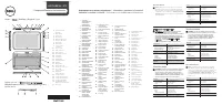 Dell Latitude 10 User Manual
-User-Manual/webp/1.webp) Dell Latitude 14 Rugged Extreme (7404, Mid 2014) User Manual
Dell Latitude 14 Rugged Extreme (7404, Mid 2014) User Manual Dell Latitude 14 Rugged Extreme 7404 User Manual
 Dell Latitude 100L User Manual
 Dell Latitude 131L User Manual
 Dell Latitude 2100 User Manual
 Dell Latitude 2110 User Manual
 Dell Latitude 3330 User Manual
 Dell Latitude ATG D620 Troubleshooting Guide
 Dell Latitude C400 User Manual