Dell Inspiron 1420 - User Manual

Dell Inspiron 1420 – User Manual, read for free online in PDF format. We hope this helps you resolve any issues you may have. If you have further questions, please contact us through the contact form.


Table of Contents:
- Page 2 – Before You Begin; Recommended Tools; Before Working Inside Your Computer
- Page 4 – Flashing the BIOS
- Page 5 – Removing and Replacing Internal Card With Bluetooth
- Page 6 – Camera Module; Removing and Replacing the Camera Module
- Page 7 – Removing the Coin-Cell Battery; Replacing the Coin-Cell Battery
- Page 9 – Microprocessor Module; Removing the Microprocessor Module
- Page 10 – Replacing the Microprocessor Module
- Page 12 – Microprocessor Thermal-Cooling Assembly; Removing the Microprocessor Thermal-Cooling Assembly; Replacing the Microprocessor Thermal-Cooling Assembly
- Page 14 – Display; Removing the Display Assembly
- Page 15 – Replacing the Display Assembly
- Page 16 – Removing the Display Bezel
- Page 18 – Replacing the Display Panel
- Page 20 – Fan; Removing the Fan
- Page 22 – Removing the FCM; Replacing the FCM
- Page 24 – Hard Drive; Removing the Hard Drive
- Page 25 – Replacing the Hard Drive
- Page 26 – Keyboard Cover; Removing the Keyboard Cover; Replacing the Keyboard Cover
- Page 27 – Keyboard; Removing the Keyboard; Replacing the Keyboard
- Page 29 – Memory; Removing the Memory Module
- Page 30 – Replacing the Memory Module
- Page 31 – Communication Cards; Removing a WLAN Card
- Page 32 – Replacing a WLAN Card; Removing a Mobile Broadband or WWAN Card
- Page 33 – Replacing a WWAN Card
- Page 34 – Modem; Removing and Replacing the Modem
- Page 35 – Optical Drive; Removing the Optical Drive; Replacing the Optical Drive
- Page 36 – Palm Rest; Removing the Palm Rest
- Page 37 – Replacing the Palm Rest
- Page 39 – Pin Assignments for I/O Connectors; USB Connector
- Page 41 – Speakers; Removing the Speakers
- Page 43 – System Board; Removing the System Board
- Page 44 – Replacing the System Board
Dell™ Inspiron™ 1420/Dell Vostro™ 1400
Service Manual
Notes, Notices, and Cautions
Information in this document is subject to change without notice.
© 2007 Dell Inc. All rights reserved.
Reproduction in any manner whatsoever without the written permission of Dell Inc. is strictly forbidden.
T r a d e m a r k s u s e d i n t h i s t e x t :
Dell
, t h e
DELL
l o g o ,
Inspiron
, a n d
Vostro
a r e t r a d e m a r k s o f D e l l I n c . ;
Intel
i s a r e g i s t e r e d t r a d e m a r k o f I n t e l C o r p o r a t i o n ;
Microsoft
,
Windows
, a n d
Windows Vista
a r e e i t h e r t r a d e m a r k s o r r e g i s t e r e d t r a d e m a r k s o f M i c r o s o f t C o r p o r a t i o n i n t h e U n i t e d S t a t e s a n d / o r o t h e r c o u n t r i e s ; B l u e t o o t h i s a r e g i s t e r e d t r a d e m a r k o w n e d b y
B l u e t o o t h S I G , I n c . a n d i s u s e d b y D e l l u n d e r l i c e n s e .
O t h e r t r a d e m a r k s a n d t r a d e n a m e s m a y b e u s e d i n t h i s d o c u m e n t t o r e f e r t o e i t h e r t h e e n t i t i e s c l a i m i n g t h e m a r k s a n d n a m e s o r t h e i r p r o d u c t s . D e l l I n c . d i s c l a i m s a n y
p r o p r i e t a r y i n t e r e s t i n t r a d e m a r k s a n d t r a d e n a m e s o t h e r t h a n i t s o w n .
S e p t e m b e r 2 0 0 9 R e v . A 0 1
Microprocessor Thermal-Cooling Assembly
Pin Assignments for I/O Connectors
NOTE:
A NOTE indicates important information that helps you make better use of your computer.
NOTICE:
A NOTICE indicates either potential damage to hardware or loss of data and tells you how to avoid the problem.
CAUTION:
A CAUTION indicates a potential for property damage, personal injury, or death.
NOTE:
The appearance of your computer may vary from what is shown in this document.
"Loading the manual" means you need to wait until the file loads and becomes available for online reading. Some manuals are very large, and the time they take to appear depends on your internet speed.
Was this manual helpful?
About this manual
- Brand
- Dell
- Model
- Inspiron 1420
- Document type
- User Manual
- Language(s)
- English
- Pages
- 45
- File size
- 1.3 MB
- Format
Summary
Back to Contents Page Before You Begin Dell™ Inspiron™ 1420/Dell Vostro™ 1400 Service Manual Recommended Tools Turning Off Your Computer Before Working Inside Your Computer This section provides procedures for removing and installing the components in your computer. Unless otherwise note...
Back to Contents Page Flashing the BIOS Dell™ Inspiron™ 1420/Dell Vostro™ 1400 Service Manual 1. Download the BIOS utility from the Dell Support website at support.dell.com and save it to your desktop. 2. After the download completes, double-click the BIOS utility file. 3. In the Dell BIOS ...
Back to Contents Page Internal Card With Bluetooth ® Wireless Technology Dell™ Inspiron™ 1420/Dell Vostro™ 1400 Service Manual Removing and Replacing Internal Card With Bluetooth ® Wireless Technology Removing and Replacing Internal Card With Bluetooth ® Wireless Technology If you...
Ask a question
Related manuals
Popular Dell Other
More Dell Other models
 Dell Inspiron 710M User Manual
 Dell Inspiron 1000 User Manual
 Dell Inspiron 1011 User Manual
 Dell Inspiron 1012 User Manual
 Dell Inspiron 1200 Troubleshooting Guide
 Dell Inspiron 1410 User Manual
- Dell Inspiron 1428 User Manual
 Dell Inspiron 1464 User Manual
 Dell Inspiron 1470 User Manual
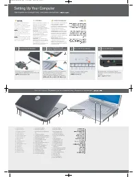 Dell Inspiron 1520 User Manual
 Dell Inspiron 1521 User Manual
 Dell INSPIRON 1525 User Manual