Dell Dimension 5100 - User Manual

Dell Dimension 5100 – User Manual, read for free online in PDF format. We hope this helps you resolve any issues you may have. If you have further questions, please contact us through the contact form.


Table of Contents:
- Page 2 – About Your DellTM; Front View of the Computer
- Page 3 – Back View of the Computer
- Page 8 – Before You Begin; Getting Started; Recommended Tools; Before Working Inside Your Computer
- Page 12 – Replacing the Computer Cover
- Page 14 – Removing the Computer Cover
- Page 16 – Removing and Installing Parts; Memory; DDR2 Memory Overview
- Page 17 – Installing Memory
- Page 18 – Cards; PCI Cards
- Page 19 – Installing a PCI Card
- Page 21 – Removing a PCI Card; PCI Express Cards; Installing a PCI Express Card
- Page 24 – Removing a PCI Express Card; Drive Panel; Removing the Drive Panel
- Page 25 – Removing the Drive-Panel Insert
- Page 27 – Front Panel; Removing the Front Panel; Drives
- Page 29 – Hard Drive; Removing a Hard Drive
- Page 30 – Installing a Hard Drive
- Page 31 – Adding a Second Hard Drive; Floppy Drive
- Page 32 – Removing a Floppy Drive
- Page 33 – Installing a Floppy Drive
- Page 34 – Removing a Media Card Reader
- Page 35 – Installing a Media Card Reader
- Page 36 – Removing a CD/DVD Drive
- Page 37 – Installing a CD/DVD Drive
- Page 38 – Removing the Heat-Sink Assembly
- Page 39 – Processor; Removing the Processor
- Page 40 – Installing the Processor
- Page 41 – Fan Assembly; Removing the Fan Assembly
- Page 42 – Removing the Front I/O Panel
- Page 43 – System Board; Jumper Settings
- Page 44 – Removing the System Board
- Page 45 – Replacing the System Board; Power Supply; Removing the Power Supply
- Page 46 – Replacing the Power Supply
- Page 80 – System Setup; Overview; System Setup Screens
- Page 81 – System Setup Options
- Page 83 – Boot Sequence; Option Settings; Changing Boot Sequence for Future Boots
- Page 84 – Clearing Forgotten Passwords
- Page 85 – Clearing CMOS Settings
- Page 92 – Specifications
- Page 98 – Technical Overview; Inside View of Your Computer; System Board Components
- Page 99 – Power Supply DC Connector Pin Assignments; DC Main Power Connector P1
- Page 101 – DC Peripheral Connectors P8 and P9
- Page 107 – Advanced Troubleshooting; When to Use the Dell Diagnostics; Starting the Dell Diagnostics From Your Hard Drive
- Page 108 – Dell Diagnostics Main Menu; System Lights
- Page 109 – Diagnostic Lights
- Page 110 – Beep Codes
Dell™ Dimension™ 5100 Service Manual
About Your Dell™ Dimension™ 5100 Computer
Notes, Notices, and Cautions
If you purchased a Dell™ n Series computer, any references in this document to Microsoft®
W i n d o w s
®
operating systems are not applicable.
Information in this document is subject to change without notice.
© 2005 Dell Inc. All rights reserved.
Reproduction in any manner whatsoever without the written permission of Dell Inc.
is strictly forbidden.
T r a d e m a r k s u s e d i n t h i s t e x t :
Dell
, t h e
DELL
l o g o , a n d
Dimension
a r e t r a d e m a r k s o f D e l l I n c . ;
Intel
a n d
Pentium
a r e r e g i s t e r e d t r a d e m a r k s o f I n t e l C o r p o r a t i o n ;
Microsoft
a n d
Windows
a r e r e g i s t e r e d t r a d e m a r k s o f M i c r o s o f t C o r p o r a t i o n .
O t h e r t r a d e m a r k s a n d t r a d e n a m e s m a y b e u s e d i n t h i s d o c u m e n t t o r e f e r t o e i t h e r t h e e n t i t i e s c l a i m i n g t h e m a r k s a n d n a m e s o r t h e i r p r o d u c t s . D e l l I n c . d i s c l a i m s a n y
p r o p r i e t a r y i n t e r e s t i n t r a d e m a r k s a n d t r a d e n a m e s o t h e r t h a n i t s o w n .
Model DCSM
October 2005 Rev. A01
NOTE:
A NOTE indicates important information that helps you make better use of your computer.
NOTICE:
A NOTICE indicates either potential damage to hardware or loss of data and tells you how to avoid the problem.
CAUTION:
A CAUTION indicates a potential for property damage, personal injury, or death.
"Loading the manual" means you need to wait until the file loads and becomes available for online reading. Some manuals are very large, and the time they take to appear depends on your internet speed.
Was this manual helpful?
About this manual
- Brand
- Dell
- Model
- Dimension 5100
- Document type
- User Manual
- Language(s)
- English
- Pages
- 116
- File size
- 3.8 MB
- Format
Summary
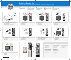
Back to Contents Page About Your Dell™ Dimension™ 5100 Computer Dell™ Dimension™ 5100 Service Manual Front View of the Computer Back View of the Computer Front View of the Computer 1 cover latch release Use this latch to remove the computer cover . 2 location of Service Tag Use the Servic...
Back View of the Computer NOTICE: Do not lift or carry the computer by the vents to avoid damage to the computer. NOTICE: Keep the vent area clean and dust-free to ensure that the computer is adequately ventilated. Use only a dry cloth to clean the vent area to avoid water damage to the comput...
Back to Contents Page Before You Begin Dell™ Dimension™ 5100 Service Manual Getting Started Recommended Tools Turning Off Your Computer Before Working Inside Your Computer Getting Started This section provides procedures for removing and installing the components in your computer. Un...
Ask a question
Related manuals
Popular Dell Other
More Dell Other models
 Dell Dimension 4500S User Manual
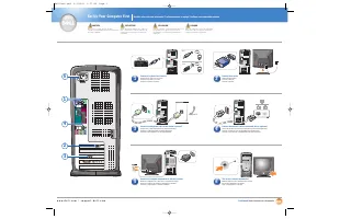 Dell Dimension 4550 User Manual
 Dell Dimension 4600 User Manual
 Dell Dimension 4600C User Manual
- Dell Dimension 4700 User Manual
 Dell Dimension 4700C User Manual
- Dell Dimension 5100C User Manual
 Dell Dimension 5150C User Manual
 Dell Dimension 8100 User Manual
 Dell Dimension 8200 User Manual
 Dell Dimension 8250 User Manual
 Dell Dimension 8300 User Manual