Page 2 - REVISION 0; USA
COPYRIGHT 2003 CANON INC. CANOSCAN 9900F REV.0 FEB. 2003 PRINTED IN JAPAN (IMPRIME AU JAPON) FEB. 2003 JY8-1322-00Z REVISION 0 SERVICEMANUAL CanoScan 9900FJPN 8132A001AA USA 8132A002AA EUR 8132A003AA UYW000001- UK 8132A004AA AUS 8132A005AA CAN/CLA 8132A006AA
Page 3 - COPYRIGHT © 2003 CANON INC.
COPYRIGHT 2003 CANON INC. CANOSCAN 9900F REV.0 FEB. 2003 PRINTED IN JAPAN (IMPRIME AU JAPON) COPYRIGHT © 2003 CANON INC. Printed in Japan Imprimè au Japon Use of this manual should be strictly supervised to avoid disclosure of confidential information.
Page 4 - CONTENTS; D. Document Scanning Sequence; CHAPTER 3 : MECHANICAL SYSTEM; A. Removing the Film Adapter Unit
COPYRIGHT 2003 CANON INC. CANOSCAN 9900F REV.0 FEB. 2003 PRINTED IN JAPAN (IMPRIME AU JAPON) CONTENTS I. SPECIFICATIONS ....................... 1-1 II. PARTS CONFIGURATION ........... 1-2 A. Front View .......................... 1-2 B. Back View ........................... 1-4 III. SETTING UP THE ...
Page 5 - TROUBLESHOOTING FLOWCHART; CHAPTER 5 : TROUBLESHOOTING; PERIODICAL REPLACEMENT; CHAPTER 6 : PARTS CATALOG
COPYRIGHT 2002 CANON INC. CANOSCAN 8000F REV.0 OCT. 2002 PRINTED IN JAPAN (IMPRIME AU JAPON) I. INTRODUCTION ........................ 5-1 A. Initial Check ....................... 5-1 B. Others ................................. 5-1 II. TROUBLESHOOTING FLOWCHART ........................................
Page 6 - CHAPTER 1; IV. CUSTOMER’S DAILY MAINTENANCE
COPYRIGHT 2003 CANON INC. CANOSCAN 9900F REV.0 FEB. 2003 PRINTED IN JAPAN (IMPRIME AU JAPON) CHAPTER 1 GENERAL DESCRIPTIONS I. SPECIFICATIONS ....................... 1-1 II. PARTS CONFIGURATION ........... 1-2 A. Front View .......................... 1-2 B. Back View ........................... 1-...
Page 8 - II. PARTS CONFIGURATION
CHAPTER 1 1 - 2 COPYRIGHT 2003 CANON INC. CANOSCAN 9900F REV.0 FEB. 2003 PRINTED IN JAPAN (IMPRIME AU JAPON) q Document Cover w Protective Sheet e Film Adapter Unit r Document Glass t COPY Button y SCAN Button u FILE Button i E-MAIL Button o Alignment Mark !0 Lock Switch II. PARTS CONFIGURATION A....
Page 9 - Power Connector
CHAPTER 1 1 - 3 COPYRIGHT 2003 CANON INC. CANOSCAN 9900F REV.0 FEB. 2003 PRINTED IN JAPAN (IMPRIME AU JAPON) B. Back View Figure 1-2 q Power Connector w FAU Cable e FAU Connector r IEEE-1394 Connector t USB Connector 5 4 3 1 2
Page 10 - Lock Switch; B. Unlocking the Lock Switch; Note : Ensure to lock the lock switch during transport.; III. SETTING UP THE SCANNER; Do not install the scanner in a humid or dusty environment.
CHAPTER 1 1 - 4 COPYRIGHT 2003 CANON INC. CANOSCAN 9900F REV.0 FEB. 2003 PRINTED IN JAPAN (IMPRIME AU JAPON) q Lock Switch B. Unlocking the Lock Switch Scanning unit is locked by the lock switch to prevent a damage during transport. Unlock thelock switch by pushing it toward the “unlock” mark to u...
Page 11 - C. Connecting Cables
CHAPTER 1 1 - 5 COPYRIGHT 2003 CANON INC. CANOSCAN 9900F REV.0 FEB. 2003 PRINTED IN JAPAN (IMPRIME AU JAPON) q USB Connector w IEEE-1394 Connector e Power Connector r USB Cable t IEEE-1394 Cable y AC Adapter C. Connecting Cables CanoScan 9900F needs to be connected to the USB port on the host comp...
Page 12 - Alignment Mark
CHAPTER 1 1 - 6 COPYRIGHT 2003 CANON INC. CANOSCAN 9900F REV.0 FEB. 2003 PRINTED IN JAPAN (IMPRIME AU JAPON) q Alignment Mark D. Scanning 1. Scanning Original 1) Place an original face-down on the document glass by aligning its top edge with the alignment mark. Figure 1-5 2) Close the document cov...
Page 14 - FILM Mark
CHAPTER 1 1 - 8 COPYRIGHT 2003 CANON INC. CANOSCAN 9900F REV.0 FEB. 2003 PRINTED IN JAPAN (IMPRIME AU JAPON) q FILM Mark 3) Place the loaded film guide by aligning its leading tab with FILM mark on the document glass and close the document cover. Figure 1-8 4) Send the scan command from the host c...
Page 15 - ) Completely wipe water off the document glass with a dry cloth.
CHAPTER 1 1 - 9 COPYRIGHT 2003 CANON INC. CANOSCAN 9900F REV.0 FEB. 2003 PRINTED IN JAPAN (IMPRIME AU JAPON) IV. CUSTOMER’S DAILY MAINTENANCE Dirt on the document glass may result in an unclear image or lines on an image. Clean thedocument glass according to the following steps. 1) Disconnect all ...
Page 16 - CHAPTER 2
COPYRIGHT 2003 CANON INC. CANOSCAN 9900F REV.0 FEB. 2003 PRINTED IN JAPAN (IMPRIME AU JAPON) CHAPTER 2 OPERATION AND TIMING I. BASIC OPERATION .................... 2-1 A. Functions ............................ 2-1 B. Electrical System ................ 2-2 C. Main PCB Input and Output . 2-4 D. Docu...
Page 19 - Functions of Main PCB; Supplies power to the drive motor.
CHAPTER 2 2 - 3 COPYRIGHT 2003 CANON INC. CANOSCAN 9900F REV.0 FEB. 2003 PRINTED IN JAPAN (IMPRIME AU JAPON) 2. Functions of Main PCB 1) Analog IC Converts the image signals (analog signals) read by CCD into digital data. - CDS (Correlated Double Sampling) - AGC (Auto Gain Control) - 8-bit A/D con...
Page 20 - C. Main PCB Input and Output
CHAPTER 2 2 - 4 COPYRIGHT 2003 CANON INC. CANOSCAN 9900F REV.0 FEB. 2003 PRINTED IN JAPAN (IMPRIME AU JAPON) JP6-1 -2 -3 -4 Power LED H o m e P o s i t i o n S e n s o r "H" when scanning unit is in home position Drive motor drive signal JP2-1 -2-3-4-5-6-7-8 Scanner button Button PCB HOTKE...
Page 21 - Document Scanning Sequence
CHAPTER 2 2 - 5 COPYRIGHT 2003 CANON INC. CANOSCAN 9900F REV.0 FEB. 2003 PRINTED IN JAPAN (IMPRIME AU JAPON) Standby Scanning Unit forward Drive Motor Sequence Home Position Sensor Scanning Lamp ON Signal Interface Signal Scan Command Setup Standby Scanning Unit backward (Scans 9 lines for RGB eac...
Page 23 - B. Lamp Lighting Circuit
CHAPTER 2 2 - 7 COPYRIGHT 2003 CANON INC. CANOSCAN 9900F REV.0 FEB. 2003 PRINTED IN JAPAN (IMPRIME AU JAPON) Host Computer ASIC GND CCD PCB GND Inverter PCB Scanning Lamp Main PCB LAMP CCD Document Glass Lens FARE Unit Scanning Unit B. Lamp Lighting Circuit 1. Scanning Lamp Lighting Circuit When t...
Page 24 - FAU Lamp Lighting Circuit; The FAU lamp also has a lamp OFF function for energy saving.; Infrared LED Lighting Circuit
CHAPTER 2 2 - 8 COPYRIGHT 2003 CANON INC. CANOSCAN 9900F REV.0 FEB. 2003 PRINTED IN JAPAN (IMPRIME AU JAPON) 2. FAU Lamp Lighting Circuit Figure 2-7 is a FAU Lamp Lighting Circuit diagram.When the host computer sends a film scanning command, ASIC turns off the scanning lamplighting signal (LAMP) a...
Page 25 - Film
CHAPTER 2 2 - 9 COPYRIGHT 2003 CANON INC. CANOSCAN 9900F REV.0 FEB. 2003 PRINTED IN JAPAN (IMPRIME AU JAPON) C. FARE (Film Automatic Retouching and Enhancement) 1. Outline When scanning a film, it is difficult to obtain a clean image because of dirt and scrach on thefilm. CanoScan 9900F is equippe...
Page 26 - Operating FARE Function
CHAPTER 2 2 - 10 COPYRIGHT 2003 CANON INC. CANOSCAN 9900F REV.0 FEB. 2003 PRINTED IN JAPAN (IMPRIME AU JAPON) Figure 2-9-1 Figure 2-9-2 Figure 2-9-3 2. Operating FARE Function Two light sources mounted in CanoScan 9900F have different frequencies ( the FAU lamp(cold cathode fluorescent lamp): 380-...
Page 27 - D. Motor Control Circuit
CHAPTER 2 2 - 11 COPYRIGHT 2003 CANON INC. CANOSCAN 9900F REV.0 FEB. 2003 PRINTED IN JAPAN (IMPRIME AU JAPON) D. Motor Control Circuit Figure 2-10 is a motor drive circuit diagram. Control program analizes a command sent from the host computer, and sends a motor clockgeneration command to ASIC. Ga...
Page 28 - III. IMAGE PROCESSING
CHAPTER 2 2 - 12 COPYRIGHT 2003 CANON INC. CANOSCAN 9900F REV.0 FEB. 2003 PRINTED IN JAPAN (IMPRIME AU JAPON) III. IMAGE PROCESSING A. Outline Image processing system consists of the CCD, analog IC, and ASIC. Analog signal read by theCCD is converted into digital data, and the digital date is sent...
Page 30 - ) Offset Calibration
CHAPTER 2 2 - 14 COPYRIGHT 2003 CANON INC. CANOSCAN 9900F REV.0 FEB. 2003 PRINTED IN JAPAN (IMPRIME AU JAPON) 3. Calibration When scanning a document of even density, the image signal corresponding to each pixel maybe uneven due to the following reasons: * Uneven light intensity of the scanning la...
Page 31 - ) Interpolation Processing
CHAPTER 2 2 - 15 COPYRIGHT 2003 CANON INC. CANOSCAN 9900F REV.0 FEB. 2003 PRINTED IN JAPAN (IMPRIME AU JAPON) 1) Interpolation Processing When scanning at higher resolution, the image quality tends to be reduced. This is becauseone pixel output from the CCD is treated as two image data in the hori...
Page 33 - A. Control System Diagram
CHAPTER 2 2 - 17 COPYRIGHT 2003 CANON INC. CANOSCAN 9900F REV.0 FEB. 2003 PRINTED IN JAPAN (IMPRIME AU JAPON) IV. CONTROL SYSTEM A. Control System Diagram Figure 2-17 B. Main PCB The scanner is not equipped with CPU. Control program in the device driver installed in thehost computer includes a con...
Page 34 - Signal Definitons
CHAPTER 2 2 - 18 COPYRIGHT 2003 CANON INC. CANOSCAN 9900F REV.0 FEB. 2003 PRINTED IN JAPAN (IMPRIME AU JAPON) 2. Signal Definitons USB uses only two identification signal lines (D+ and D-) to communicate with the hostcomputer. Table 2-2 3. Interface Connection USB connector has two plugs: A plug f...
Page 35 - Outline of IEEE 1394 Standard; connector without power supply; Signal Definition
CHAPTER 2 2 - 19 COPYRIGHT 2003 CANON INC. CANOSCAN 9900F REV.0 FEB. 2003 PRINTED IN JAPAN (IMPRIME AU JAPON) B. IEEE 1394 1. Outline of IEEE 1394 Standard IEEE is a standard for high-speed serial interface called "Firewire" or "i.LINK"Features of IEEE 1394 includes: 1. No host com...
Page 37 - CHAPTER 3
COPYRIGHT 2003 CANON INC. CANOSCAN 9900F REV.0 FEB. 2003 PRINTED IN JAPAN (IMPRIME AU JAPON) CHAPTER 3 MECHANICAL SYSTEM I. PARTS REPLACEMENT .............. 3-1 A. Precautions ......................... 3-1 II. EXTERNALS .............................. 3-2 A. Removing the Film Adapter Unit ............
Page 39 - FAU Cable
CHAPTER 3 3 - 2 COPYRIGHT 2003 CANON INC. CANOSCAN 9900F REV.0 FEB. 2003 PRINTED IN JAPAN (IMPRIME AU JAPON) q FAU Cable w Film Adapter Unit II. EXTERNALS A. Removing the Film Adapter Unit 1) Disconnect the FAU cable.2) Lift the film adapter unit as shown in Figure 3-1 to remove it. Figure 3-1 1 2
Page 40 - Screw; B. Removing the Top Cover and the Document Glass Unit
CHAPTER 3 3 - 3 COPYRIGHT 2003 CANON INC. CANOSCAN 9900F REV.0 FEB. 2003 PRINTED IN JAPAN (IMPRIME AU JAPON) q Screw w Top Cover e Hook B. Removing the Top Cover and the Document Glass Unit 1) Remove two screws that hold the Top Cover .2) Remove the Top Cover by holding the front part of the cover...
Page 41 - Document Glass Unit; C. Attaching the Front Panel
CHAPTER 3 3 - 4 COPYRIGHT 2003 CANON INC. CANOSCAN 9900F REV.0 FEB. 2003 PRINTED IN JAPAN (IMPRIME AU JAPON) Figure 3-3 3) Slide the document glass unit backward and lift it. Remove the glass from the scanner. q Document Glass Unit 1 C. Attaching the Front Panel 1) Make sure that corners of the To...
Page 42 - D. Removing the Front Panel; Hook
CHAPTER 3 3 - 5 COPYRIGHT 2003 CANON INC. CANOSCAN 9900F REV.0 FEB. 2003 PRINTED IN JAPAN (IMPRIME AU JAPON) D. Removing the Front Panel 1) Remove the Front Panel from the scanner. (Refer to III-A Removing the Main PCB)2) Remove the Top Cover and the Document Glass.3) Remove the Carriage Unit and ...
Page 43 - button PCB unit from the main frame.
CHAPTER 3 3 - 6 COPYRIGHT 2003 CANON INC. CANOSCAN 9900F REV.0 FEB. 2003 PRINTED IN JAPAN (IMPRIME AU JAPON) 6) Press two hooks on both sides of the front panel inward. Remove the front panel and the button PCB unit from the main frame. q Front Panel w Button PCB Unit e Hook Figure 3-5 3 2 1 3
Page 44 - Cable Band
CHAPTER 3 3 - 7 COPYRIGHT 2003 CANON INC. CANOSCAN 9900F REV.0 FEB. 2003 PRINTED IN JAPAN (IMPRIME AU JAPON) 7) Cut off cable bands and disconnect cables from the main frame. Remove the button PCB unit. q Cable Band Figure 3-6 1
Page 45 - ) Remove three screws and remove the button cable board.
CHAPTER 3 3 - 8 COPYRIGHT 2003 CANON INC. CANOSCAN 9900F REV.0 FEB. 2003 PRINTED IN JAPAN (IMPRIME AU JAPON) 8) Remove three screws and remove the button cable board. q Screw w Button PCB e Lower Button Cover Figure 3-7 1 3 2
Page 46 - E. Attaching the Front Panel
CHAPTER 3 3 - 9 COPYRIGHT 2003 CANON INC. CANOSCAN 9900F REV.0 FEB. 2003 PRINTED IN JAPAN (IMPRIME AU JAPON) E. Attaching the Front Panel 1) Pass the button cables through the main frame.2) Fix cables to the main frames with cable bands as shown in Figure 3-8 q Cable Band Figure 3-8 1
Page 48 - A. Removing the Main PCB; ) Turn the scanner over and remove four screws.
CHAPTER 3 3 - 11 COPYRIGHT 2003 CANON INC. CANOSCAN 9900F REV.0 FEB. 2003 PRINTED IN JAPAN (IMPRIME AU JAPON) q Screw w Main PCB III. PCBs A. Removing the Main PCB 1) Turn the scanner over and remove four screws. Figure 3-10 1 2
Page 49 - Motor Unit Cable
CHAPTER 3 3 - 12 COPYRIGHT 2003 CANON INC. CANOSCAN 9900F REV.0 FEB. 2003 PRINTED IN JAPAN (IMPRIME AU JAPON) 2) Lift the main PCB as shown in Figure 3-11 and disconnect the button cable and the motor unit cable. q Motor Unit Cable w Button Cable Figure 3-11 1 2
Page 50 - Remove the main PCB from the main frame.
CHAPTER 3 3 - 13 COPYRIGHT 2003 CANON INC. CANOSCAN 9900F REV.0 FEB. 2003 PRINTED IN JAPAN (IMPRIME AU JAPON) 3) Turn the main PCB over. Remove screw that holds grounding and the flat cable. Remove the main PCB from the main frame. q Main PCB w Flat Cable e Screw Figure 3-12 1 3 2
Page 51 - A. Removing the Scanning Unit
CHAPTER 3 3 - 14 COPYRIGHT 2003 CANON INC. CANOSCAN 9900F REV.0 FEB. 2003 PRINTED IN JAPAN (IMPRIME AU JAPON) IV. OPTICAL SYSTEM A. Removing the Scanning Unit Note: Lens and mirrors of the scanning unit are factory adjusted. Do not touch the lamp, mirrors, and CCD PCB (shaded area shown in Figure ...
Page 54 - Grounding Cable
CHAPTER 3 3 - 17 COPYRIGHT 2003 CANON INC. CANOSCAN 9900F REV.0 FEB. 2003 PRINTED IN JAPAN (IMPRIME AU JAPON) 5) Remove two screws that hold the gear plate 2 . Remove spring from the gear plate 2.6) Remove screw that holds grounding. q Grounding Cable w Screw e Spring r Gear Plate 2 Figure 3-16 No...
Page 57 - ) Slide the slidng rod backward and lift it as shown in Figure 3-19.
CHAPTER 3 3 - 20 COPYRIGHT 2003 CANON INC. CANOSCAN 9900F REV.0 FEB. 2003 PRINTED IN JAPAN (IMPRIME AU JAPON) 9) Slide the slidng rod backward and lift it as shown in Figure 3-19. Disconnec the motor connector. Remove the sliding unit first and the scanning unit out ofthe main frame. q Document Sc...
Page 58 - Scanning Unit
CHAPTER 3 3 - 21 COPYRIGHT 2003 CANON INC. CANOSCAN 9900F REV.0 FEB. 2003 PRINTED IN JAPAN (IMPRIME AU JAPON) 10) Remove the sliding rod and the timing belt from the scanning unit. q Scanning Unit w Sliding Rod Figure 3-20 1 2
Page 59 - B. Removing Motor Unit; Sliding Rod
CHAPTER 3 3 - 22 COPYRIGHT 2003 CANON INC. CANOSCAN 9900F REV.0 FEB. 2003 PRINTED IN JAPAN (IMPRIME AU JAPON) B. Removing Motor Unit 1) Remove the main PCB.2) Remove the top cover and the document glass.3) Remove the scanning unit.4) Remove a screw that holds the sliding rod to the motor unit. q S...
Page 60 - C. Attaching the Motor Unit; frame. Make sure that no grease be applied to other parts.
CHAPTER 3 3 - 23 COPYRIGHT 2003 CANON INC. CANOSCAN 9900F REV.0 FEB. 2003 PRINTED IN JAPAN (IMPRIME AU JAPON) Figure 3-22 C. Attaching the Motor Unit 1) Apply grease (EM-50L) to the shaft of the gear when attaching the motor unit to the main frame. Make sure that no grease be applied to other part...
Page 61 - CHAPTER 4
COPYRIGHT 2003 CANON INC. CANOSCAN 9900F REV.0 FEB. 2003 PRINTED IN JAPAN (IMPRIME AU JAPON) CHAPTER 4 MAINTENANCE AND SERVICING I. PERIODICAL REPLACEMENT PARTS ....................................... 4-1 II. CONSUMABLE PARTS DURABILITY .............................. 4-1 III. PERIODICAL SERVICING ...
Page 62 - I. PERIODICAL REPLACEMENT PARTS
CHAPTER 4 4 - 1 COPYRIGHT 2003 CANON INC. CANOSCAN 9900F REV.0 FEB. 2003 PRINTED IN JAPAN (IMPRIME AU JAPON) I. PERIODICAL REPLACEMENT PARTS None II. CONSUMABLE PARTS DURABILITY None III. PERIODICAL SERVICING None IV. SPECIAL TOOLS None V. SOLVENTS AND LUBRICANTS Grease used for disassembly and re...
Page 63 - CHAPTER 5
COPYRIGHT 2003 CANON INC. CANOSCAN 9900F REV.0 FEB. 2003 PRINTED IN JAPAN (IMPRIME AU JAPON) CHAPTER 5 TROUBLESHOOTING I. INTRODUCTION ........................ 5-1 A. Initial Check ....................... 5-1 B. Others ................................. 5-1 II. TROUBLESHOOTING FLOWCHART ..............
Page 64 - Line voltage is within ±10% of the rated value.
CHAPTER 5 5 - 1 COPYRIGHT 2003 CANON INC. CANOSCAN 9900F REV.0 FEB. 2003 PRINTED IN JAPAN (IMPRIME AU JAPON) I. INTRODUCTION A. Initial Check Check if the operating environment conforms to the following conditions. * Line voltage is within ±10% of the rated value. * Ambient temperature and humidit...
Page 65 - II. TROUBLESHOOTING FLOWCHART
CHAPTER 5 5 - 2 COPYRIGHT 2003 CANON INC. CANOSCAN 9900F REV.0 FEB. 2003 PRINTED IN JAPAN (IMPRIME AU JAPON) II. TROUBLESHOOTING FLOWCHART A. Power LED Failure Figure 5-1 Unlock Lock Switch Connect AC Adapter Power LED is ON ? Connect USB cable No Yes Table 5-1 Figure 5-2
Page 66 - B. Communication Failure
CHAPTER 5 5 - 3 COPYRIGHT 2003 CANON INC. CANOSCAN 9900F REV.0 FEB. 2003 PRINTED IN JAPAN (IMPRIME AU JAPON) B. Communication Failure Figure 5-2 Scan Communication failed ? Scanning Unit failed to move ? Yes Table 5-2 Yes Table 5-3 Yes Table 5-4 No Poor image quality ? No Acoustic noise originated...
Page 67 - III. PROBLEM, CAUSE AND CORRECTIVE ACTION; A. Power LED Not Lighting
CHAPTER 5 5 - 4 COPYRIGHT 2003 CANON INC. CANOSCAN 9900F REV.0 FEB. 2003 PRINTED IN JAPAN (IMPRIME AU JAPON) Possible Cause Related Parts Check Method Corrective Action USB cable connection failure Scanner communication failure Scanning unit failure USB cable Main PCB Scanning unit Visual check Tr...
Page 68 - C. Scanning Unit Movement Failure
CHAPTER 5 5 - 5 COPYRIGHT 2003 CANON INC. CANOSCAN 9900F REV.0 FEB. 2003 PRINTED IN JAPAN (IMPRIME AU JAPON) Possible Cause Related Parts Check Method Corrective Action Drive belt broken or worn Gears broken or worn Scanner button failure Drive motor failure Drive belt Pulley Unit Button PCB Motor...
Page 69 - IV. CANON SCANNER TEST; B. Operating Environment; The Canon Scanner Test requires following environment:
CHAPTER 5 5 - 6 COPYRIGHT 2003 CANON INC. CANOSCAN 9900F REV.0 FEB. 2003 PRINTED IN JAPAN (IMPRIME AU JAPON) IV. CANON SCANNER TEST A. Outline Canon Scanner Test is a utility software to check if faulty operation of CanoScan 9900F iscaused by the hardware or the communication with the host compute...
Page 70 - Scanner Information; CanoScan 9900F self test is executed.
CHAPTER 5 5 - 7 COPYRIGHT 2003 CANON INC. CANOSCAN 9900F REV.0 FEB. 2003 PRINTED IN JAPAN (IMPRIME AU JAPON) C. Functions 1. USB Information (Windows only) Information of the scanner connected to the USB port on the PC is displayed. Ifcommunication between the scanner and the host computer fails, ...
Page 71 - D. Functions Descriptions; : Port name of the scanner recognized by Windows
CHAPTER 5 5 - 8 COPYRIGHT 2003 CANON INC. CANOSCAN 9900F REV.0 FEB. 2003 PRINTED IN JAPAN (IMPRIME AU JAPON) D. Functions Descriptions 1. USB Information (Windows only) Select “USB Information” from the “Function” menu. The window shown in Figure 5-3 willappear. Figure 5-3 * Vendor Description : M...
Page 72 - : Firmware version of the control program of the scanner
CHAPTER 5 5 - 9 COPYRIGHT 2003 CANON INC. CANOSCAN 9900F REV.0 FEB. 2003 PRINTED IN JAPAN (IMPRIME AU JAPON) 2. Scanner Information Select “Scanner information” from the “Function” menu The window shown in Figure 5-4(Windows) or Figure 5-5 (Macintoch) will appear. Figure 5-4 Figure 5-5 * Vendor ID...
Page 76 - folder of the Canon Scanner Test.
CHAPTER 5 5 - 13 COPYRIGHT 2003 CANON INC. CANOSCAN 9900F REV.0 FEB. 2003 PRINTED IN JAPAN (IMPRIME AU JAPON) * Scan count Set the number to be scanned ranging from 1 to 100. * Resolution (dpi) When the resolution for scanning an image is set at 67/200/400dpi, the entire area of the document glass...
Page 79 - “Scanner has problem.” “Failed to execute scanner self test.”
CHAPTER 5 5 - 16 COPYRIGHT 2003 CANON INC. CANOSCAN 9900F REV.0 FEB. 2003 PRINTED IN JAPAN (IMPRIME AU JAPON) E. Error Message 1. “Unable to find the scanner. Check if the cables are connected properly.” Cause : Scanner is not detected by the host computer.Corrective Action : Refer to the “II. Tro...


 Canon CanoScan 4400F Quick Guide
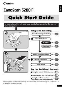 Canon CanoScan 5200F User Manual
 Canon CanoScan 8000F Quick Guide
 Canon CanoScan 8400F User Manual
 Canon CanoScan 8600F Quick Guide
 Canon CanoScan 9000F Mark II User Manual
 Canon CanoScan 9950F User Manual
 Canon CanoScan FS2710 User Manual
 Canon CanoScan LiDE 25 User Manual
 Canon CanoScan LiDe 50 User Manual
 Canon CanoScan LiDE 60 User Manual