Broan ALT230SS - User Manual

Broan ALT230SS Range Hood – User Manual, read for free online in PDF format. We hope this helps you resolve any issues you may have. If you have further questions, please contact us through the contact form.


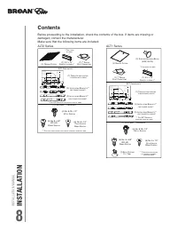


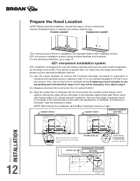


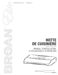
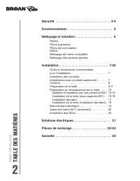
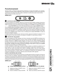
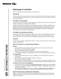
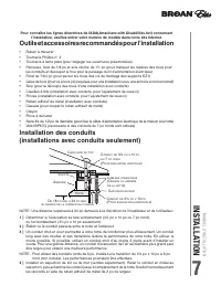
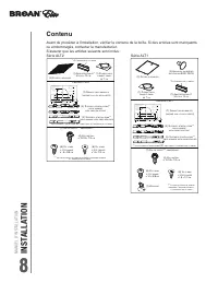
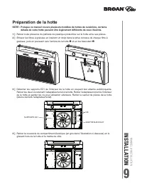
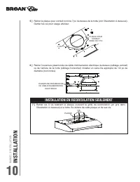
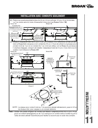
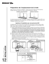
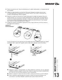
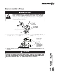
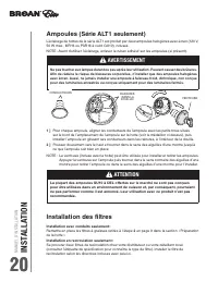
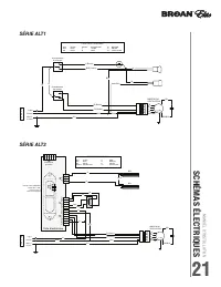
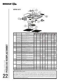
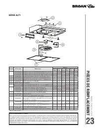
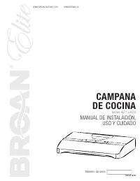


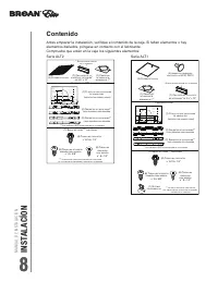


Table of Contents:
- Page 3 – Table of Contents
- Page 4 – Important Safety Notice; READ AND SAVE THESE INSTRUCTIONS
- Page 5 – CAUTION; WARNING
- Page 6 – List of Materials; PARTS NOT SUPPLIED; - Ducting, conduit and all installation tools; HARDWARE PACKAGE CONTENTS BMI; PARTS SUPPLIED; - Hood with internal blower; HARDWARE PACKAGE CONTENTS BVE
- Page 7 – Installation –
- Page 8 – DUCTING; Chart A
- Page 9 – WARNING FIRE HAZARD; Some Ducting Options; side wall cap
- Page 10 – FRONT
- Page 12 – A cable locking connector (not supplied) might
- Page 13 – Mark mounting spread from C/L on line B. From center; WARNING: Electrical wiring must be done by a qualified person(s) in
- Page 14 – RECIRCULATING KIT (REQUIRED IF NO DUCTING IS USED); Charcoal Filter Replacements; Hood Model
- Page 15 – Lights; Touch Controls
- Page 16 – Cleaning Stainless Steel; Aluminum Mesh Filters; Removing Aluminum Mesh Filters; Maintenance –
- Page 17 – LED LIGHT STRIPS; Push the clip
- Page 18 – ACT Conversion; By default the maximum blower CFM is set to 600.; To verify if your installer enabled ACT
- Page 19 – iring Diagrams
- Page 20 – TROUBLESHOOTING PROCEDURES FOR BRISAS; Issue; Troubleshooting
- Page 21 – Accessories; DESCRIPTION; Replacement Parts
WWW.BROAN-NUTONE.COM
Serial number:
99046182B
WWW.BROAN.CA
RANGE HOOD
Series: ALT1 and ALT2
INSTALLATION, USE
AND CARE MANUAL
"Loading the manual" means you need to wait until the file loads and becomes available for online reading. Some manuals are very large, and the time they take to appear depends on your internet speed.
Summary
INSTALLATION MANUAL SAFETY 3 READ AND SAVE THESE INSTRUCTIONS ! Intended for domestic cooking only ! INSTALLER: LEAVE THIS MANUAL WITH HOMEOWNER. In U.S.A., register your range hood online at www.broan-nutone.com In Canada, register your range hood online at www.broan.ca ! WARNING TO REDUCE THE RISK...
INST ALLA TION MANUAL SAFETY 4 ! WARNING TO REDUCE THE RISK OF A RANGE TOP GREASE FIRE: a) Never leave surface units unattended at high settings. Boilovers cause smoking and greasy spillovers that may ignite. Heat oils slowly on low or medium settings. b) Always turn hood ON when cooking at high hea...
INSTALLATION MANUAL OPERA TION 5 Operation Always turn your hood on before you begin cooking to establish an air flow in the kitchen. Let the blower run for a few minutes to clear the air after you turn off the range. This will help keep the whole kitchen cleaner and fresher. Operate the hood as fol...