Zephyr DVL-E36ASSX - Manuals
User Manual Zephyr DVL-E36ASSX


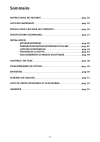


Summary
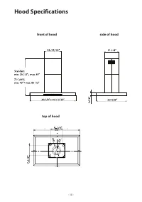
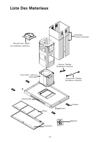
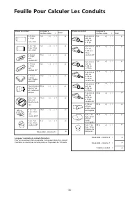
Table of Contents SAFETY INSTRUCTIONS .................................................................................................. pag. 4 LIST OF MATERIALS ........................................................................................................... pag. 8 DUCTING CALCULATION SHE...
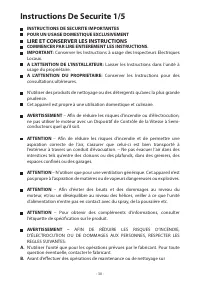
IMPORTANT SAFETY INSTRUCTIONS FOR RESIDENTIAL USE ONLY READ AND SAVE THESE INSTRUCTIONS PLEASE READ ENTIRE INSTRUCTIONS BEFORE PROCEEDING. IMPORTANT : Save these Instructions for the Local Electrical Inspectors use. INSTALLER : Please leave these Instructions with this unit for the owner. OWNER : Pl...
ing and greasy spillovers that may ignite. Heat oils slowly on low or medium settings. B. Always turn hood ON when cooking at high heat or when flambeing foods ( i.e. Crepes Suzette, Cherries Jubilee, Peppercorn Beef Flambè ). C. Clean ventilating fans frequently. Grease should not be allowed to acc...
Zephyr Range Hoods Manuals
-
 Zephyr AK1100BB
User Manual
Zephyr AK1100BB
User Manual
-
 Zephyr AK1100BS
User Manual
Zephyr AK1100BS
User Manual
-
Zephyr AK1100BW
User Manual
-
Zephyr AK1124BS
User Manual
-
Zephyr AK1124BW
User Manual
-
 Zephyr AK1136BB
User Manual
Zephyr AK1136BB
User Manual
-
 Zephyr AK1136BS
User Manual
Zephyr AK1136BS
User Manual
-
 Zephyr AK1136BW
User Manual
Zephyr AK1136BW
User Manual
-
 Zephyr AK1200CB
User Manual
Zephyr AK1200CB
User Manual
-
 Zephyr AK1200CBS
User Manual
Zephyr AK1200CBS
User Manual
-
Zephyr AK1200CS
User Manual
-
 Zephyr AK1200CW
User Manual
Zephyr AK1200CW
User Manual
-
Zephyr AK1236CB
User Manual
-
 Zephyr AK1236CBS
User Manual
Zephyr AK1236CBS
User Manual
-
Zephyr AK1236CS
User Manual
-
Zephyr AK1236CW
User Manual
-
 Zephyr AK2100CB
User Manual
Zephyr AK2100CB
User Manual
-
 Zephyr AK2100CS
User Manual
Zephyr AK2100CS
User Manual
-
 Zephyr AK2100CW
User Manual
Zephyr AK2100CW
User Manual
-
 Zephyr AK2136CB
User Manual
Zephyr AK2136CB
User Manual