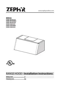
Zephyr DME-M90ASGX - Manuals
User Manual Zephyr DME-M90ASGX


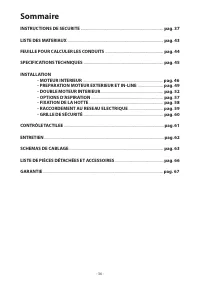


Summary
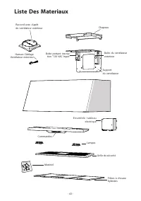
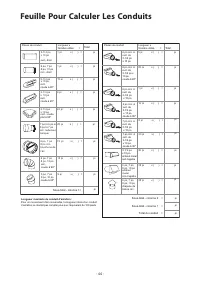
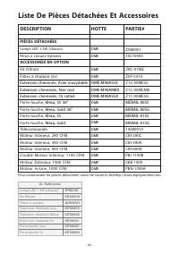
Table of Contents SAFETY INSTRUCTIONS ................................................................................................ pag. 4 LIST OF MATERIALS ......................................................................................................... pag. 9 DUCTING CALCULATION SHEETS ...
IMPORTANT SAFETY INSTRUCTIONS FOR RESIDENTIAL USE ONLY READ AND SAVE THESE INSTRUCTIONS PLEASE READ ENTIRE INSTRUCTIONS BEFORE PROCEEDING. IMPORTANT : Save these Instructions for the Local Electrical Inspectors use. INSTALLER : Please leave these Instructions with this unit for the owner. OWNER : Pl...
Safety instructions 2/5 WARNING - TO REDUCE THE RISK OF A RANGE TOP GREASE FIRE: A. Never leave surface units unattended at high settings. Boilovers cause smok- ing and greasy spillovers that may ignite. Heat oils slowly on low or medium settings. B. Always turn hood ON when cooking at high heat or ...
Zephyr Range Hoods Manuals
-
 Zephyr AK1100BB
User Manual
Zephyr AK1100BB
User Manual
-
 Zephyr AK1100BS
User Manual
Zephyr AK1100BS
User Manual
-
Zephyr AK1100BW
User Manual
-
Zephyr AK1124BS
User Manual
-
Zephyr AK1124BW
User Manual
-
 Zephyr AK1136BB
User Manual
Zephyr AK1136BB
User Manual
-
 Zephyr AK1136BS
User Manual
Zephyr AK1136BS
User Manual
-
 Zephyr AK1136BW
User Manual
Zephyr AK1136BW
User Manual
-
 Zephyr AK1200CB
User Manual
Zephyr AK1200CB
User Manual
-
 Zephyr AK1200CBS
User Manual
Zephyr AK1200CBS
User Manual
-
Zephyr AK1200CS
User Manual
-
 Zephyr AK1200CW
User Manual
Zephyr AK1200CW
User Manual
-
Zephyr AK1236CB
User Manual
-
 Zephyr AK1236CBS
User Manual
Zephyr AK1236CBS
User Manual
-
Zephyr AK1236CS
User Manual
-
Zephyr AK1236CW
User Manual
-
 Zephyr AK2100CB
User Manual
Zephyr AK2100CB
User Manual
-
 Zephyr AK2100CS
User Manual
Zephyr AK2100CS
User Manual
-
 Zephyr AK2100CW
User Manual
Zephyr AK2100CW
User Manual
-
 Zephyr AK2136CB
User Manual
Zephyr AK2136CB
User Manual