Whirlpool WEC310SAGS - Manuals
Whirlpool WEC310SAGS Range – User Manual in PDF format online.
Manuals:
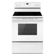
User Manual Whirlpool WEC310SAGS


Summary
2 RANGE SAFETY Your safety and the safety of others are very important. We have provided many important safety messages in this manual and on your appliance. Always read and obey all safetymessages. This is the safety alert symbol. This symbol alerts you to potential hazards that can kill or hurt yo...
4 RANGE MAINTENANCE ANDCARE Self-Cleaning Cycle (on somemodels) WARNING Burn Hazard Do not touch the oven during the Self-Cleaning cycle. Keep children away from the oven during Self-Cleaningcycle. Failure to follow these instructions can result in burns. IMPORTANT: The health of some birds is extre...
6 Cleaning Method: � Mild detergent OVEN CAVITY Do not use oven cleaners. Food spills should be cleaned when oven cools. At hightemperatures, foods react with porcelain. Staining, etching, pitting,or faint white spots can result. Cleaning Method: � Clean cycle: See the “Self-Cleaning Cycle” section....
Whirlpool Ranges Manuals
-
 Whirlpool ACM 501
User Manual
Whirlpool ACM 501
User Manual
-
 Whirlpool ACM 503
User Manual
Whirlpool ACM 503
User Manual
-
 Whirlpool ACM 562
User Manual
Whirlpool ACM 562
User Manual
-
 Whirlpool AER6303MFB
User Manual
Whirlpool AER6303MFB
User Manual
-
 Whirlpool AER6303MFW
User Manual
Whirlpool AER6303MFW
User Manual
-
 Whirlpool AKM 513
User Manual
Whirlpool AKM 513
User Manual
-
 Whirlpool LWFR7200S
User Manual
Whirlpool LWFR7200S
User Manual
-
 Whirlpool LWFR7300S
User Manual
Whirlpool LWFR7300S
User Manual
-
 Whirlpool WEC310S0LB
User Manual
Whirlpool WEC310S0LB
User Manual
-
Whirlpool WEC310S0LB
Manual
-
 Whirlpool WEC310S0LS
User Manual
Whirlpool WEC310S0LS
User Manual
-
Whirlpool WEC310S0LS
Manual
-
 Whirlpool WEC310S0LW
User Manual
Whirlpool WEC310S0LW
User Manual
-
Whirlpool WEC310S0LW
Manual
-
 Whirlpool WEE510S0FS
User Manual
Whirlpool WEE510S0FS
User Manual
-
Whirlpool WEE510S0FS
Manual
-
Whirlpool WEE510S0FS
Installation Manual
-
 Whirlpool WEE515S0LB
User Manual
Whirlpool WEE515S0LB
User Manual
-
Whirlpool WEE515S0LB
Manual
-
 Whirlpool WEE515S0LS
User Manual
Whirlpool WEE515S0LS
User Manual