Page 2 - CONTENTS; WELCOME 3; To purchase accessories for your tool, visit
2 CONTENTS WELCOME 3 Introduction ......................................................................................................3Specifications ................................................................................................... 3 SAFETY 4 General Safety Rules ...................
Page 3 - INTRODUCTION; safety for both yourself and others.; SPECIFICATIONS
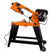
INTRODUCTION Thanks for purchasing the WEN Metal Bandsaw. We know you are excited to put your tool to work, but first, please take a moment to read through the manual. Safe operation of this tool requires that you read and understand this operator’s manual and all the labels affixed to the tool. Thi...
Page 4 - GENERAL SAFETY RULES; WORK AREA SAFETY
GENERAL SAFETY RULES 4 5 WORK AREA SAFETY 1. Keep work area clean and well lit. Cluttered or dark areas invite accidents. 2. Do not operate power tools in explosive atmo- spheres, such as in the presence of flammable liq- uids, gases or dust. Power tools create sparks which may ignite the dust or fu...
Page 5 - POWER TOOL USE AND CARE
GENERAL SAFETY RULES 4 5 7. If devices are provided for the connection of dust extraction and collection facilities, ensure these are connected and properly used. Use of dust collection can reduce dust-related hazards. POWER TOOL USE AND CARE 1. Do not force the power tool. Use the correct power too...
Page 6 - SAW BLADE SAFETY; PERSONAL SAFETY; SPECIFIC RULES FOR YOUR METAL BANDSAW
SAW BLADE SAFETY 1. Always wear protective gloves when handling saw blades. 2. Only use blades with correct size and type for both your Metal Bandsaw and your workpiece. • The size of the saw blade is 64-1/2 x 1/2 inches. • The blade material is bimetal with 14 TPI. 3. Never use damaged or deformed ...
Page 7 - DURING CUTTING OPERATIONS
2. Ensure that work is correctly supported. Supports must be placed under the workpiece on both sides, close to the line of cut and near the edge of the work- piece. 3. For accuracy of cut, and to avoid blade binding, al- ways use a rip fence or straight edge guide. 4. Never hand-hold a workpiece th...
Page 8 - ELECTRICAL INFORMATION; AMPERAGE; GUIDELINES AND RECOMMENDATIONS FOR EXTENSION CORDS; In the event of a malfunction or breakdown
ELECTRICAL INFORMATION 8 AMPERAGE REQUIRED GAUGE FOR EXTENSION CORDS 25 ft. 50 ft. 100 ft. 150 ft. 4.6A 18 gauge 16 gauge 14 gauge 14 gauge 3. Check with a licensed electrician or service personnel if you do not completely understand the grounding instructions or whether the tool is properly grounde...
Page 9 - UNPACKING; PACKING LIST; UNPACKING & TRANSPORTATION
UNPACKING With the help of a friend or trustworthy foe, carefully remove the Metal Bandsaw from the packaging. Make sure to take out all contents and accessories. Do not discard the packaging until everything is removed. Check the packing list below to make sure you have all of the parts and accesso...
Page 10 - KNOW YOUR METAL BANDSAW; TOOL PURPOSE
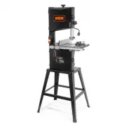
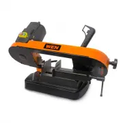
10 KNOW YOUR METAL BANDSAW TOOL PURPOSE Metal Bandsaws are used to cut flat and round pieces of metal. Refer to the following diagrams to become familiar- ized with all the parts and controls of your Metal Bandsaw. The components will be referred to later in the manual for assembly and operation ins...
Page 11 - ASSEMBLY & ADJUSTMENTS; ASSEMBLING THE STAND; Instructions continue on the next page.
ASSEMBLY & ADJUSTMENTS 11 ASSEMBLING THE STAND 1. With the help of an assistant, lift the bandsaw onto a suitable support (Fig. 2). 2. Attach the legs to the bandsaw with the M8-1.25x25 hex bolts, 8mm flat washers, 8mm lock washers, and the M8- 1.25 hex nuts. Hand tighten. 3. Attach the short br...
Page 13 - clockwise
ADJUSTING THE VISE 1. Loosen the two hex bolts on the large jaw. Use the scale as a guide to set your angle. Retighten the hex bolts. See Fig. 12. 2. Loosen the hex bolt on the small jaw. Match the angle of the workpiece. Retighten the hex bolt. See Fig. 13. 3. Use the handle (Fig. 14) to open or cl...
Page 14 - ADJUSTING THE BLADE SPEED; To change the blade’s speed:; USING THE HEAD LOCK PIN; To use the head locking pin:
ADJUSTING THE BLADE SPEED The bandsaw is capable of operating at 80, 120 or 180 FPM. The speed can easily be adjusted by changing the V- belt placement (Fig. 16). To change the blade’s speed: 1. Loosen the motor lock bolt (Fig. 17) to allow the motor to pivot freely. 2. Raise the motor to relieve th...
Page 15 - OPERATION; VERTICAL CUTTING; To assemble the bandsaw for vertical cutting:
OPERATION 15 HORIZONTAL CUTTING (FIG. 19) Use the work stop to quickly and accurately cut multiple pieces of stock to the same length. 1. Clamp the material firmly in the vise jaws to ensure a straight cut through the material. 2. Let the blade reach full speed before engaging the work- piece. Never...
Page 16 - ROUTINE INSPECTION; MAINTENANCE; REPLACING THE OIL; Please recycle the packaging and electronic
ROUTINE INSPECTION Before each use, inspect the general condition of the tool. If any of these following conditions exist, do not use until parts are replaced or the saw is properly re- paired. Check for: • Loose hardware,• Damaged or dull blades,• Misalignment or binding of moving parts, • Damaged ...
Page 17 - CHANGING THE SAW BLADE
MAINTENANCE CHANGING THE SAW BLADE 1. Use the head locking pin to lock the saw in the vertical posi- tion. Remove the blade cover screw and loosen the blade cover lock knob. See Fig. 24. Open the blade cover. 2. Move the motor-side blade guide as far as it will go toward the motor. 3. Remove the two...
Page 18 - BLADE ALIGNMENT; Using the Blade Guard to Straighten the Blade:
18 MAINTENANCE BLADE ALIGNMENT Check Blade tension: 1. Remove the black back cover and make sure the blade is properly aligned on both wheels. 2. Adjust the blade tension until the blade sits properly cen- tered (or does not move) on both wheels during operation Check Blade Guard: Without the left b...
Page 19 - TROUBLESHOOTING GUIDE
19 TROUBLESHOOTING GUIDE WARNING! Stop using the tool immediately if any of the following problems occur. Repairs and replacements should only be performed by an authorized technician. For any questions, please contact our customer service at (800) 232-1195, M-F 8-5 CST or email us at [email protect...
Page 20 - PROBLEM
20 TROUBLESHOOTING GUIDE PROBLEM POSSIBLE CAUSE SOLUTION Inaccurate cut squaring. 1. Excessive cutting pressure (incorrect choice of feed rate). 1. Decrease feed rate.2. Incorrect choice of blade tooth count. 2. Use a different blade more suited to the material type. 3. Incorrect adjustment of slidi...
Page 21 - EXPLODED VIEW & PARTS LIST
21 EXPLODED VIEW & PARTS LIST 21 NOTE: Not all parts may be available for purchase. Parts and accessories that wear down over the course of normal use are not covered under the warranty.
Page 22 - Description
EXPLODED VIEW & PARTS LIST No. Part No. Description Qty. 1 3970-001 Worm Gear Pulley 1 2 3970-002 Set Screw, M8x8 1 3 3970-003 Pan Head Screw, M4x8 1 4 3970-004 Flat Washer, 4mm 1 5 3970-005 Flat Head Screw, M4x8 2 6 3970-006 Bearing Cover 1 7 3970-007 Oil Seal 1 8 3970-008 Ball Bearing, 6202ZZ ...
Page 25 - WARRANTY
WARRANTY WEN Products is committed to building tools that are dependable for years. Our warranties are consistent with this commitment and our dedication to quality. LIMITED WARRANTY OF WEN PRODUCTS FOR HOME USE GREAT LAKES TECHNOLOGIES, LLC (“Seller”) warrants to the original purchaser only, that a...
Page 26 - NOTES