Page 2 - CONTENTS
CONTENTS English.............................................................................01 Бъ лгарски........................................................................06 Čeština.............................................................................11 Қазақша............................
Page 3 - Installation; Desktop Installation; Set the device on a flat surface strong enough to support
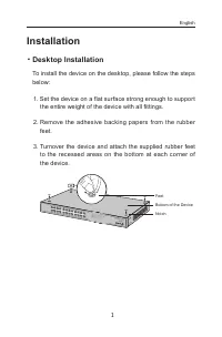
1 Installation ■ Desktop Installation To install the device on the desktop, please follow the steps below: 1. Set the device on a flat surface strong enough to support the entire weight of the device with all fittings. 2. Remove the adhesive backing papers from the rubber feet. 3. Turnover the devic...
Page 4 - Rack Installation; Check the grounding and stability of the rack.
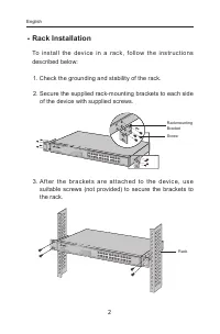
2 ■ Rack Installation To install the devic e in a rack, follow the instr uctions described below: 1. Check the grounding and stability of the rack. 2. Secure the supplied rack-mounting brackets to each side of the device with supplied screws. RackmountingBracketScrew 3. Af ter the brac ket s are at ...
Page 5 - Connection; Ethernet Port
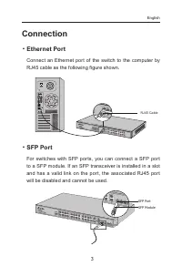
3 Connection ■ Ethernet Port Connect an Ethernet port of the switch to the computer by RJ45 cable as the following figure shown. RJ45 Cable ■ SFP Port For switches with SFP ports, you can connect a SFP port to a SFP module. If an SFP transceiver is installed in a slot and has a valid link on the por...
Page 7 - Configuration; Configure the Switch Using the GUI
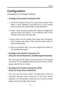
5 Configuration (Unavailable for Unmanaged Switches) ■ Configure the Switch Using the GUI 1. Set the IP address of your PC in the same subnet of the switch. The IP address is 192.168.0.x("x" is any number from 2 to 254); the Subnet Mask is 255.255.255.0. 2. Open a web browser and type the de...
Page 8 - Инсталация; Настолен монтаж
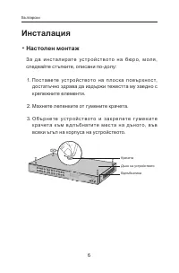
6 Инсталация ■ Настолен монтаж З а д а и н с т а л и р а т е у с т р о й с т в о т о н а б ю р о, м о л я , следвайте стъпките, описани по-долу: 1. П о с т а в ете ус т р о й с т в о т о н а п л о с к а п о в ърх н о с т, достатъчно здрава да издържи тежестта му заедно с крепежните елементи. 2. Махн...
Page 9 - Инсталация в шкаф / стелаж; Проверете заземяването и стабилността на шкафа.; След като скобите са закрепени към устройството,
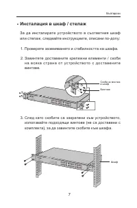
7 ■ Инсталация в шкаф / стелаж За да инсталирате устройството в съответния шкаф или стелаж, следвайте инструкциите, описани по-долу: 1. Проверете заземяването и стабилността на шкафа. 2. Завинтете доставените крепежни елементи / скоби н а в с я к а с т р а н а от ус т р о й с т в ото с до с та в е н...
Page 10 - Свързване; Ethernet порт
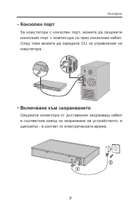
8 Свързване ■ Ethernet порт Свържете Ethernet порта на суича към компютъра чрез RJ45 кабел, както е показано на следващата фигура. RJ45 кабел ■ SFP порт При суичове с SFP портове, можете да свържете SFP порта към SFP модул. Ако SFP трансивър е инсталиран в слот и има валиден линк на порта, ас оциира...
Page 12 - Конфигуриране
10 Конфигуриране (Недостъпно за неуправляеми комутатори) ■ Ко н ф и г у р и р а н е н а с у ич а с и з п о л з в а н е н а графичния потребителски интерфейс 1. Поставете IP адреса на вашия РС в една и съща подмрежа със суича. IP адресът е 192.168.0.x("x" е произволно число от 2 до 254); Маск...
Page 13 - Instalace; Stolní instalace; Položte zařízení na plochý povrch dostatečně silný, aby
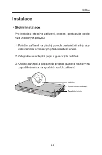
11 Instalace ■ Stolní instalace Pro instalaci stolního zařízení, prosím, postupujte podle níže uvedených pokynů: 1. Položte zařízení na plochý povrch dostatečně silný, aby celé zařízení s veškerým příslušenstvím unesl. 2. Odejměte samolepící papír z gumových nožiček. 3. Otočte zařízení a připevněte ...
Page 14 - Instalace do stojanu; Zkontrolujte uzemnění a stabilitu racku.; Jakmile jsou podpěr y připevněny k zařízení, použijte
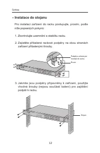
12 ■ Instalace do stojanu Pro instalaci zařízení do racku postupujte, prosím, podle níže popsaných pokynů: 1. Zkontrolujte uzemnění a stabilitu racku. 2. Zajistěte přibalené rackové podpěry na obou stranách zařízení přibalenými šrouby. Podpěra určená pro montáž do racku Šroub 3. Jakmile jsou podpěr ...
Page 15 - Připojení; Port Ethernet
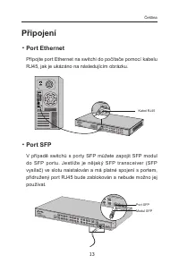
13 Připojení ■ Port Ethernet Připojte port Ethernet na switchi do počítače pomocí kabelu RJ45, jak je ukázáno na následujícím obrázku. Kabel RJ45 ■ Port SFP V případě switchů s porty SFP můžete zapojit SFP modul do SFP por tu. Jestliže je nějaký SFP transceiver (SFP vysílač) ve slotu naistalován a m...
Page 17 - Konfigurace; Nakonf igur ujt e swi tch pomocí u ž ivat elského
15 Konfigurace (Nedostupné pro Neřízené Switche) ■ Nakonf igur ujt e swi tch pomocí u ž ivat elského průvodce instalací 1. Nastavte IP adresu vašeho PC ve stejné podsíti swtiche. IP adresa je 192.168.0.x ("x" je jakékoli číslo od 2 do 254); maska podsítě je 255.255.255.0. 2. Otevřete webový ...
Page 18 - Орнату; Үстелге орнату
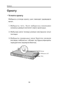
16 Орнату ■ Үстелге орнату Жабдықты үстелде орнату үшін төмендегі қадамдарға еріңіз: 1. Ж а б д ы қ т ы т е г і с , б ү к і л ж а б д ы қ т ы ң ж и н а ғ ы м е н салмағын демеуге жеткілікті жерге орнатыңыз. 2. Жабысқақ қағаз төсемді резеңке аяқтарынан алып тастаңыз. 3. Ж а б д ы қ т ы а у д а р ы ң ...
Page 19 - Тіреуге орнату; Т і р еу і ш т і ң ж е р г е т ұ й ы қ т ау ы м е н т ұ р а қ т ы л ы ғ ы н
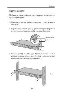
17 ■ Тіреуге орнату Жабдықты тіреуге орнату үшін төменде сипатталған нұсқауларға еріңіз: 1. Т і р еу і ш т і ң ж е р г е т ұ й ы қ т ау ы м е н т ұ р а қ т ы л ы ғ ы н тексеріңіз. 2. Берілген тіреуішті орнат у ұстауыштарды берілген винттермен жабдықтың әрбір жағынан бекітіңіз. Тіреуішке орнату ұстау...
Page 20 - Қосылу
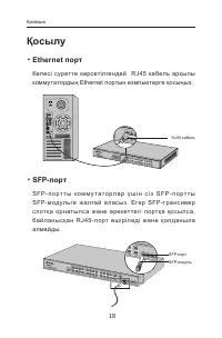
18 Қосылу ■ Ethernet порт Келесі суретте көрсетілгендей RJ45 кабель арқылы коммутатордың Ethernet портын компьютерге қосыңыз. RJ45 кабель ■ SFP-порт S F P - п о р т т ы к о м м у т а т о р л а р ү ш і н с і з S F P - п о р т т ы SFP- модульге жа л ғай а лас ыз. Егер SFP-транс ивер с лотқ а орнатылс ...
Page 22 - (Басқарылмайтын коммутаторлар үшін қол жетімсіз); Қ о л д а н у ш ы н ы ң г р а ф и к а л ы қ и н т е р ф е й с і н
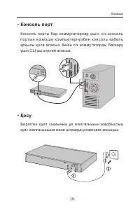
20 Орнату (Басқарылмайтын коммутаторлар үшін қол жетімсіз) ■ Қ о л д а н у ш ы н ы ң г р а ф и к а л ы қ и н т е р ф е й с і н қолданып коммутаторды баптаңыз. 1. Ө з і ң і з д і ң д е р б е с к о м п ь ю т е р і ң і з д і ң I P - а д р е с і н бағдарғылауыштың басқару интерфейсіндегідей бір кіші жел...
Page 23 - Įrengimas; Stacionari instaliacija
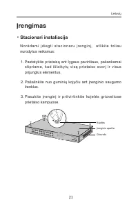
21 Įrengimas ■ Stacionari instaliacija N o r ė d a m i į d i e g t i s t a c i o n a r u į r e n g i n į, a t l i k i t e t o l i a u nurodytus veiksmus: 1. Pastatykite prietaisą ant lygaus paviršiaus, pakankamai stipr iame, kad išlaik y tų visą pr ietaiso svor į ir visus prijungtus elementus. 2. Pa...
Page 24 - Spintos įrengimas; Patikrinkite įžeminimą ir stabilumą spintoje.; Kaip pritvir tinsite montavimo elementus, turite įrengti
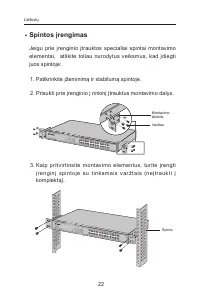
22 ■ Spintos įrengimas Jeigu prie įrenginio įtrauktos specialiai spintai montavimo elementai, atlikite toliau nurodytus veiksmus, kad įdiegti juos spintoje: 1. Patikrinkite įžeminimą ir stabilumą spintoje. 2. Prisukti prie įrenginio į rinkinį įtrauktus montavimo dalys. Montavimo laikiklis Varžtas 3....
Page 25 - Įrenginio prisijungimas; Ethernet prievadas
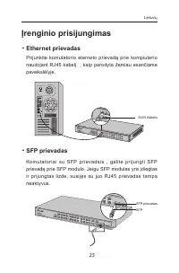
23 Įrenginio prisijungimas ■ Ethernet prievadas Prijunkite komutatorio eterneto prievadą prie kompiuterio naudojant RJ45 kabelį , kaip parodyta žemiau esančiame paveikslėlyje. RJ45 Kabelis ■ SFP prievadas Komutator iai su SFP pr ievadais , galite pr ijungti SFP prievadą prie SFP modulo. Jeigu SFP mo...
Page 26 - P r i j u n k i t e m o t e r i š k a m a i t i n i m o l a i d o g a l ą p r i e
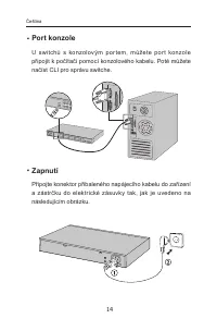
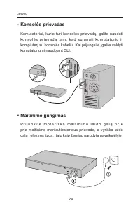
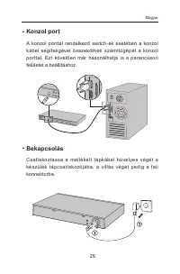
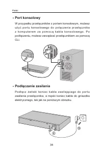
24 ■ Konsolės prievadas Komutatoriai, kurie turi konsolės prievadą, galite naudoti ko n s o l ė s p r i ev a d ą t a m , k a d s u j u n g t i ko m u t a t o r i ų i r kompiuterį su konsolės kabeliu. Kai prijungsite, galite valdyti komutatoriumi naudojant CLI. ■ Maitinimo įjungimas P r i j u n k i t...
Page 27 - Konfigūracija; Komutatorio konfigūracija, naudojant valdymo
25 Konfigūracija (Neprieinami nevaldomiems komutatoriams) ■ Komutatorio konfigūracija, naudojant valdymo sąsaja. 1. Pr i e š p r i s i jun gi ant p r i e m a r š r ut iz ato r i aus va l dy m o s ą s a j o s , t u r i t e n u s t a t y t i ko m p i u t e r i u i f i k s u o t ą I P diapazone 192.168...
Page 28 - Beüzemelés; Asztali beüzemelés
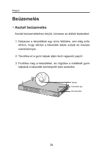
26 Beüzemelés ■ Asztali beüzemelés Asztali beüzemeléshez kérjük, kövesse az alábbi lépéseket: 1. Helyezze a készüléket egy sima felületre, ami elég erős ahhoz, hogy elbírja a készülék teljes súlyát az összes szerelvénnyel. 2. Távolítsa el a gumi talpak alján lévő ragasztó papírt. 3. Fordítsa meg a k...
Page 29 - Rack szekrénybe illesztés
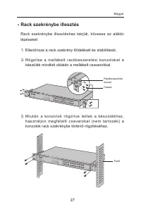
27 ■ Rack szekrénybe illesztés Rack szekrénybe illesztéshez kérjük, kövesse az alábbi lépéseket: 1. Ellenőrizze a rack szekrény földelését és stabilitását. 2. Rö gzít se a mellékelt rac k bes zerelési konzolokat a készülék mindkét oldalán a mellékelt csavarokkal. Rackbeszerelési konzol Csavar 3. M i...
Page 30 - Csatlakozás; Ethernet csatlakozás
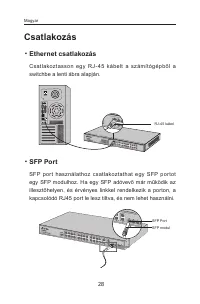
28 Csatlakozás ■ Ethernet csatlakozás Csatlakoztasson egy RJ - 45 kábelt a számítógépből a switchbe a lenti ábra alapján. RJ-45 kábel ■ SFP Port SFP por t használathoz csatlakoztathat egy SFP por tot egy SFP modulhoz. Ha egy SFP adóvevő már működik az illesztőhelyen, és érvényes linkkel rendelkezik ...
Page 32 - Beállítás; Konfigurálás webes felületen keresztül
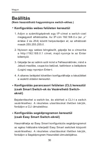
30 Beállítás (Nem használható hagyományos switch-ekhez.) ■ Konfigurálás webes felületen keresztül 1. Adjon a számítógépének egy IP- címet a switch- csel megegyező alhálózatba. Az IP-cím 192.168.0.x (az „x” értéke 2 és 254) között helyezkedjen el; az alhálózati maszk 255.255.255.0 . 2. Nyisson egy we...
Page 33 - Instalacja; Na blacie
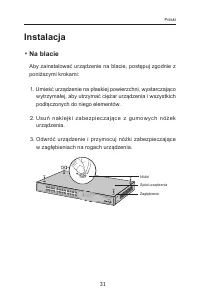
31 Instalacja ■ Na blacie Aby zainstalować urządzenie na blacie, postępuj zgodnie z poniższymi krokami: 1. Umieść urządzenie na płaskiej powierzchni, wystarczająco wytrzymałej, aby utrzymać ciężar urządzenia i wszystkich podłączonych do niego elementów. 2. Usuń naklejki zabezpiec zając e z gumow yc ...
Page 34 - W szafie; Sprawdź uziemienie i stabilność szafy.; Po zamocowaniu elementów montażowych, zamontuj
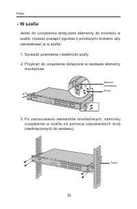
32 ■ W szafie Jeżeli do urządzenia dołączono elementy do montażu w szafie, możesz postąpić zgodnie z poniższymi krokami, aby zainstalować je w szafie: 1. Sprawdź uziemienie i stabilność szafy. 2. Przykręć do urządzenia dołączone w zestawie elementy montażowe. Element montażowyŚruba 3. Po zamocowaniu...
Page 35 - Podłączanie urządzenia
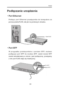
33 Podłączanie urządzenia ■ Port Ethernet Pod ł ąc z por t Ether net pr ze ł ąc znika do komputera z a pomocą kabla RJ45, tak jak na poniższym obrazku. Kabel RJ45 ■ Port SFP W p r z y p a dk u p r ze ł ą c z n i ków z p o r t a m i S FP, m o ż e s z podłączyć por t SFP do modułu SFP. Jeżeli moduł SF...
Page 37 - Konfiguracja; Konfiguracja przełącznika za pomocą interfejsu
35 Konfiguracja (Niedostępne dla przełączników niezarządzalnych.) ■ Konfiguracja przełącznika za pomocą interfejsu zarządzania 1. Pr zed z alogowaniem si ę do inter fejsu z ar z ądz ania przełącznikiem przydziel komputerowi stały adres IP z podsieci 192.168.0.x (gdzie x to liczba z zakresu 2-254); m...
Page 38 - Установка; Установка на столе
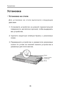
36 Установка ■ Установка на столе Д л я у с т а н о в к и н а с т о л е в ы п о л н и т е с л е д у ю щ и е действия: 1. Установите устройство на ровной горизонтальной поверхности, достаточно прочной, чтобы выдержать вес устройства. 2. Уд а лите з ащитну ю к лейк у ю бумаг у с р е з ин овых ножек. 3...
Page 39 - Установка в стойке
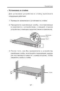
37 ■ Установка в стойке Д л я у с т а н о в к и у с т р о й с т в а в с т о й к у в ы п о л н и т е следующие действия: 1. Проверьте заземление и устойчивость стойки. 2. П р и к р е п и т е к р е п ё ж н ы е с к о б ы , п о с т а в л я е м ы е в к о м п л е к т е с у с т р о й с т в о м , к к а ж д ...
Page 40 - Подключение; Порт Ethernet
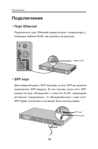
38 Подключение ■ Порт Ethernet Подключите порт Ethernet коммутатора к компьютеру с помощью кабеля RJ45, как указано на рисунке. Кабель RJ45 ■ SFP порт Для коммутаторов с SFP портами, в слот SFP вы можете подключить SFP-модуль. В том случае, если слот SFP ко мму тато ра о бъ е дин ё н с п о рто м RJ4...
Page 42 - Настройка; (Недоступно для неуправляемых коммутаторов )
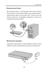
40 Настройка (Недоступно для неуправляемых коммутаторов ) ■ Настройка коммутатора через веб- страницу управления 1. Н а с т р о й т е I P - а д р е с в а ш е г о к о м п ь ю т е р а т а к и м о б р а з о м , ч т о б ы о н б ы л в о д н о й п о д с е т и с комму татором. Должен быть установлен IP-адр...
Page 43 - Instalare; Instalare pe birou; Așez ați dispozitivul pe o suprafață plană și suf icient de
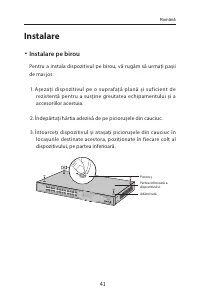
41 Instalare ■ Instalare pe birou Pentru a instala dispozitivul pe birou, vă rugăm să urmați pașii de mai jos: 1. Așez ați dispozitivul pe o suprafață plană și suf icient de rezistentă pentru a susține greutatea echipamentului și a accesoriilor acestuia. 2. Îndepărtați hârtia adezivă de pe piciorușe...
Page 44 - Instalare în rack; Verificați împământarea electrică și stabilitatea rack-ului.; D up ă ce sup o r tur il e sunt at aș ate la disp oziti v, utiliz ați
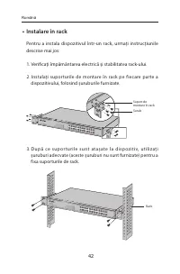
42 ■ Instalare în rack Pentru a instala dispozitivul într-un rack, urmați instrucțiunile descrise mai jos: 1. Verificați împământarea electrică și stabilitatea rack-ului. 2. Instalați suporturile de montare în rack pe fiecare parte a dispozitivului, folosind șuruburile furnizate. Suport de montare î...
Page 45 - Conectare
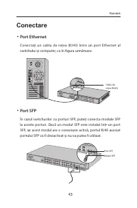
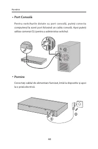
43 Conectare ■ Port Ethernet Conectați un cablu de rețea (RJ45) între un port Ethernet al switchului și computer, ca în figura următoare. Cablu de rețea (RJ45) ■ Port SFP În cazul switchurilor cu porturi SFP, puteți conecta module SFP la aceste porturi. Dacă un modul SFP este instalat într-un port S...
Page 47 - Configurare; (Indisponibil pentru switchurile fără management); Configurați switchul folosind Interfața Grafică (GUI); Configurați adresa IP a PC-ului astfel încât aceasta să fie în; Configurați switchul utilizând CLI
45 Configurare (Indisponibil pentru switchurile fără management) ■ Configurați switchul folosind Interfața Grafică (GUI) 1. Configurați adresa IP a PC-ului astfel încât aceasta să fie în aceeași subrețea cu adresa IP a interfeței de administrare a routerului. Adresa IP a PC-ului trebuie să fie 192.1...
Page 48 - Inštalácia; Inštalácia na pracovný stôl
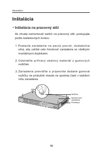
46 Inštalácia ■ Inštalácia na pracovný stôl Ak chcete namontovať switch na pracovný stôl, postupujte podľa nasledovných krokov: 1. Po s t av te z a r i a d e n i e n a p ev ný p ov r c h, d o st ato č n e silný, aby udržal celú hmotnosť zariadenia so všetkými montážnymi doplnkami. 2. O d s t r á ň t...
Page 49 - Inštalácia do racku; Skontrolujte ukotvenie a stabilitu racku.; Po pr ipevnení konzol k z ar iadeniu p oužite vho dné
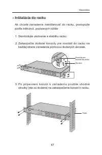
47 ■ Inštalácia do racku Ak chcete zariadenie nainštalovať do racku, postupujte podľa inštrukcií, popísaných nižšie: 1. Skontrolujte ukotvenie a stabilitu racku. 2. Zabezpečte dodané konzoly pre montáž do racku na každej strane zariadenia pomocou dodaných skrutiek. Konzola pre montáž do racku Skrutk...
Page 50 - Zapojenie; Ethernetový konektor
48 Zapojenie ■ Ethernetový konektor Pripojte ethernetový konektor switchu k počítaču pomocou kábla RJ45 tak, ako je to vyobrazené na obrázku. Kábel RJ45 ■ Port SFP Pre switche s por tami SFP môžete k por tu SFP pripojiť modul SFP. Ak je prijímač s vysielačom SFP nainštalovaný v zásuvke a má platný l...
Page 52 - Konfigurácia; (Nie je dostupné pre prepínače bez správy); Nakonfigurujte switch pomocou GUI
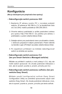
50 Konfigurácia (Nie je dostupné pre prepínače bez správy) ■ Nakonfigurujte switch pomocou GUI 1. N ast av te I P adre su svojh o P C v r ov nakej p o dsi et i switchu. IP adresa je 192.168.0.x ("x" je ktorékoľvek číslo od 2 do 254); maska podsiete je 255.255.255.0. 2. Otvorte webový prehlia...
Page 53 - Povezivanje; Postavljanje na stolu
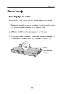
51 Povezivanje ■ Postavljanje na stolu Za pravilno povezivanje uređaja pratite sledeća uputstva: 1. Postavite uređaj na ravnu površinu koja je dovoljno jaka da izdrži težinu uređaja sa svim priključcima. 2. Uklonite zaštitne nalepnice sa gumenih stopica. 3. Okrenite uređaj naopako i postavite gumene...
Page 54 - Postavljanje u rek
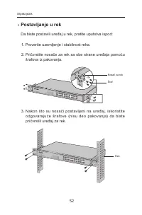
52 ■ Postavljanje u rek Da biste postavili uređaj u rek, pratite uputstva ispod: 1. Proverite uzemljenje i stabilnost reka. 2. Pričvrstite nosače za rek sa obe strane uređaja pomoću šrafova iz pakovanja. Nosač za rek Šraf 3. Nakon što su nosači postavljeni na uređaj, iskoristite odgovarajuće šrafove...
Page 55 - Mrežni port
53 Povezivanje ■ Mrežni port Povežite mrežni por t sviča sa računarom pomoću RJ45 kabla kao što je prikazano na slici. RJ45 kabl ■ SFP Port Kod svič eva sa SFP por tovima, možete povezati SFP por t sa SFP modulom. Ako je instaliran SFP transiver i ima dobru vezu na portu, odgovarajući RJ45 port će b...
Page 57 - Podešavanje; Podešavanje sviča pomoću GUI-a; i lozinku, oba malim slovima. Zatim kliknite Login ili; Podešavanje sviča pomoću CLI-a; uputstvo za Utility program.
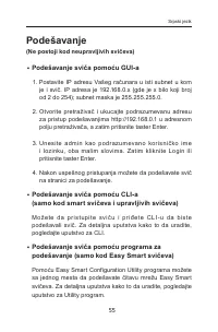
55 Podešavanje (Ne postoji kod neupravljivih svičeva) ■ Podešavanje sviča pomoću GUI-a 1. Postavite IP adresu Vašeg računara u isti subnet u kom je i svič. IP adresa je 192.168.0.x (gde je x bilo koji broj od 2 do 254); subnet maska je 255.255.255.0. 2. Otvorite pretraživač i ukucajte podrazumevanu ...
Page 58 - Установка на столі; Ус тан о віть прис трій на пл о с к ій п о верх ні, до с ить
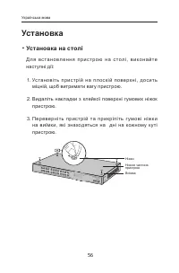
56 Установка ■ Установка на столі Д л я в с т а н о в л е н н я п р и с т р о ю н а с т о л і , в и к о н а й т е наступні дії: 1. Ус тан о віть прис трій на пл о с к ій п о верх ні, до с ить міцній, щоб витримати вагу пристрою. 2. Видаліть накладки з клейкої поверхні гумових ніжок пристрою. 3. Пер ...
Page 59 - Установка пристрою у стійку; Перевірте заземлення та стабільність стійки.; П і с л я п р и к р і п л е н н я к р о н ш т е й н і в д о п р и с т р о ю,
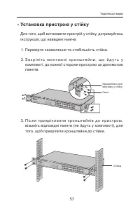
57 ■ Установка пристрою у стійку Для того, щоб встановити пристрій у стійку, дотримуйтесь інструкцій, що наведені нижче: 1. Перевірте заземлення та стабільність стійки. 2. З а к р і п і т ь м о н т а ж н і к р о н ш т е й н и , щ о й д у т ь у комплекті, до кожної сторони пристрою за допомогою гвинт...
Page 60 - Підключення; Ethernet порт
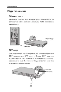
58 Підключення ■ Ethernet порт З'єднайте Ethernet порт комутатора з комп'ютером за допомогою cat 5e кабелю з роз’ємом RJ45, як вказано на малюнку. Кабель cat 5e з роз’ємом RJ45 ■ SFP порт Для комутаторів з SFP портами: Ви можете під'єднати S F P м о д у л ь д о S F P п о р т у. Я к щ о S F P м о д у...
Page 62 - Налаштування; (Не використовується для некерованих комутаторів); Налаштування використовуючи GUI ( графічний
60 Налаштування (Не використовується для некерованих комутаторів) ■ Налаштування використовуючи GUI ( графічний інтерфейс користувача) 1. Вс тановіть IP- а дресу вашого комп'ютера в одній підмережі з комутатором. IP-адреса 192.168.0.x ("х" є будь -яке чис ло ві д 2 до 25 4); Мас ка пі дмереж...
Page 63 - Namestitev; Namizna namestitev; Napravo postavite na stabilno plosko površino, ki lahko
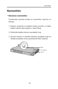
61 Namestitev ■ Namizna namestitev Upoštevajte spodnje korake za namestitev naprave na namizje: 1. Napravo postavite na stabilno plosko površino, ki lahko podpre celotno težo naprave z vsemi fitingi. 2. Odstranite lepljive trakove z gumijastih nog. 3. Obrnite napravo in pritrdite priložene gumijaste...
Page 64 - Namestitev stojala; Preverite podlago in stabilnost stojala.; Ko nosilce pritrdite na napravo, jih z ustreznimi vijaki (niso
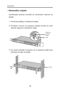
62 ■ Namestitev stojala Upoštevajte spodnja navodila za namestitev naprave na stojalo: 1. Preverite podlago in stabilnost stojala. 2. Priložene nosilce za vgradnjo stojala privijte na vseh straneh naprave s priloženimi vijaki. Nosilec za vgradnjo stojalaVijak 3. Ko nosilce pritrdite na napravo, jih ...
Page 65 - Povezava; Vrata Ethernet
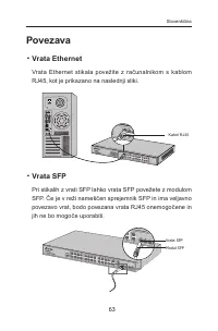
63 Povezava ■ Vrata Ethernet Vrata Ethernet stikala povežite z računalnikom s kablom RJ45, kot je prikazano na naslednji sliki. Kabel RJ45 ■ Vrata SFP Pri stikalih z vrati SFP lahko vrata SFP povežete z modulom SFP. Če je v reži nameščen sprejemnik SFP in ima veljavno povezavo vrat, bodo povezana vr...
Page 67 - Konfiguracija; Konfiguracija stikala z grafičnim vmesnikom; Odprite spletni brskalnik in vnesite privzeti naslov za; Konfiguracija stikala z vmesnikom CLI; postopek, preberite vodnik za vmesnik CLI.; Konfiguracija stikala z orodjem
65 Konfiguracija (ni na voljo za neupravljana stikala) ■ Konfiguracija stikala z grafičnim vmesnikom 1. Nastavite naslov IP računalnika v istem podomrežju s t i k a l a . N a s l ov I P j e 19 2 .16 8 . 0 . x (»x« p r e d s t av l j a poljubno število med 2 in 254); maska podomrežja je 255.255.255.0...
Page 68 - Ugradnja; Ugradnja na radni stol; Hrvatski
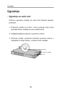
66 Ugradnja ■ Ugradnja na radni stol Prilikom ugradnje uređaja na radni stol slijedite sljedeći postupak: 1. Postavite uređaj na čvrstu i ravnu podlogu koja može podnijeti težinu uređaja sa svim priključcima. 2. Odlijepite ljepljive papiriće s gumenih nožica. 3. Okrenite uređaj i postavite priložene...
Page 69 - Modularna ugradnja; Kako biste uređaj montirali u modul, slijedite upute u
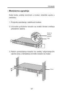
67 ■ Modularna ugradnja Kako biste uređaj montirali u modul, slijedite upute u nastavku: 1. Povjerite uzemljenje i stabilnost modula. 2. Učvrstite priložene nosač e sa svake strane uređaja priloženim vijcima. Nosač za stražnju ugradnjuVijak 3. Nakon postavljanja nosača na uređaj, odgovarajućim vijci...
Page 70 - Veza; Ethernet priključak
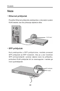
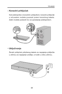
68 Veza ■ Ethernet priključak Povežite Ethernet priključak preklopnika s računalom putem RJ45 kabela, kao što prikazuje sljedeća slika. RJ45 kabel ■ SFP priključak Kod preklopnika s SFP pr iključ cima, možete povezati SFP priključak sa SFP modulom. Ako je u utor montiran SFP primopredajnik i postoji...
Page 72 - (Nedostupno za preklopnike kojima se ne upravlja); Ko n f i g u r i r a j t e p r e k l o p n i k p u t e m g r a f i č k o g; adresu i pritisnite Enter.; Konfigurirajte preklopnik putem naredbenog retka
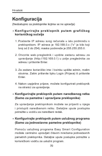
70 Konfiguracija (Nedostupno za preklopnike kojima se ne upravlja) ■ Ko n f i g u r i r a j t e p r e k l o p n i k p u t e m g r a f i č k o g korisničkog sučelja 1. Postavite IP adresu svog računala u istu podmrežu s preklopnikom. IP adresa je 192.168.0.x ("x" je bilo koji broj od 2 do 254...
Page 73 - Uzstādīšana; Instalēšana uz darbvirsmas; Novietojiet ierīci uz līdzenas, pietiekami drošas virsmas,; Latviski
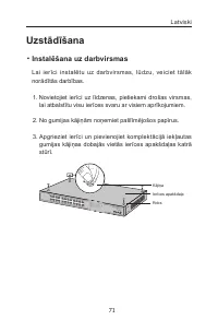
71 Uzstādīšana ■ Instalēšana uz darbvirsmas Lai ierīci instalētu uz darbvirsmas, lūdzu, veiciet tālāk norādītās darbības. 1. Novietojiet ierīci uz līdzenas, pietiekami drošas virsmas, lai atbalstītu visu ierīces svaru ar visiem aprīkojumiem. 2. No gumijas kājiņām noņemiet pašlīmējošos papīrus. 3. Ap...
Page 74 - Instalēšana uz plaukta
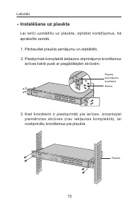
72 ■ Instalēšana uz plaukta Lai ierīci uzstādītu uz plaukta, izpildiet norādījumus, kā aprakstīts zemāk. 1. Pārbaudiet plaukta zemējumu un stabilitāti. 2. Piestipriniet komplektā iekļautos stiprinājuma kronšteinus ierīces katrā pusē ar piegādātajām skrūvēm. Plaukta stiprinājuma kronšteinsSkrūve 3. K...
Page 75 - Savienojums; Ethernet ports
73 Savienojums ■ Ethernet ports Pievienojiet slēdža Ethernet por tu datoram, izmantojot RJ45 kabeli, kā parādīts attēlā. RJ45 kabelis ■ SFP ports Slēdžiem ar SFP portiem varat izveidot savienojumu ar SFP portu uz SFP moduli. Ja SFP uztvērējs ir uzstādīts slotā un tam ir derīga saite portā, saistītai...
Page 77 - Konfigurācija; Konfigurējiet slēdzi, izmantojot GUI
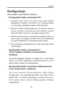
75 Konfigurācija (Nav pieejams nepārvaldītiem slēdžiem) ■ Konfigurējiet slēdzi, izmantojot GUI 1. I e s t a t i e t s a v a d a t o r a I P a d r e s i t a j ā p a š ā s l ē d ž a apakštīklā. IP adrese ir 192.168.0.x ("x" ir jebkurš skaitlis no 2 līdz 254); apakštīkla maska ir 255.255.255.0....
Page 78 - Paigaldamine; Seadme lauaar vutisse paigaldamiseks järgi alltoodud; Eesti
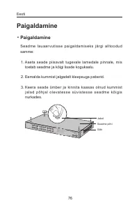
76 Paigaldamine ■ Paigaldamine Seadme lauaar vutisse paigaldamiseks järgi alltoodud samme: 1. Aseta seade piisavalt tugevale lamedale pinnale, mis toetab seadme ja kõigi lisade kogukaalu. 2. Eemalda kummist jalgadelt kleepsuga paberid. 3. Keera seade ümber ja kinnita kaasas olnud kummist j a l a d p...
Page 79 - Raami paigaldamine; Kontrolli raami maandust ja stabiilsust.
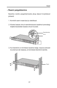
77 ■ Raami paigaldamine Seadme restile paigaldamiseks järgi allpool kirjeldatud juhiseid: 1. Kontrolli raami maandust ja stabiilsust. 2. Kinnita kaasas olnud raamikinnitused seadme kummalegi küljele kasutades kaasas olnud kruvisid. RaamikinnitusKruvi 3. Kui klambrid on kinnitatud seadme külge, kasut...
Page 80 - Ühendus; Etherneti port; Ühenda lüliti Etherneti port arvutiga RJ45 kaabli abil, nagu; SFP port; sellel on kehtiv ühendus pordiga, lülitatakse sellega seotud
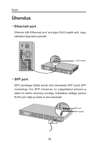
78 Ühendus ■ Etherneti port Ühenda lüliti Etherneti port arvutiga RJ45 kaabli abil, nagu näidatud järgmisel joonisel. RJ45 kaabel ■ SFP port SFP portidega lülitite korral võid ühendada SFP pordi SFP mooduliga. Kui SFP transiiver on paigaldatud pilusse ja sellel on kehtiv ühendus pordiga, lülitatakse...
Page 81 - Konsooli port; Konsooli pordiga lülitite korral võid ühendada konsooli; Toide sisse
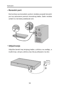
79 ■ Konsooli port Konsooli pordiga lülitite korral võid ühendada konsooli pordi konsooli kaabli abil oma ar vutiga. Siis saad lüliti haldamiseks laadida CLI. ■ Toide sisse Pane olemasoleva toitejuhtme emane konnektor seadme toitepistikusse ja isane konnektor pistikupessa. Eesti
Page 82 - Konfiguratsioon; Konfigureeri lüliti GUI abil.
80 Konfiguratsioon (Pole saadaval halduseta lülitite jaoks) ■ Konfigureeri lüliti GUI abil. 1. M ä ä r a o m a a r v u t i I P - a a d r e s s s a m a s a l a mvõ r g u s , kui lüliti. IP-aadress on 192.168.0.x ("x" on mistahes number vahemikus 2 kuni 25 4); alamvõrgu mask on 255.255.255.0. ...
Page 83 - • Do not attempt to disassemble, repair, or modif y the
English Safety Information• Keep the device away from water, fire, humidity or hot environments. • Do not attempt to disassemble, repair, or modif y the device. • Do not use damaged charger or USB cable to charge the device. • Do not use any other chargers than those recommended.Pleas e read and fol...
Page 85 - USB kabelio pagalba.
USB kabelio pagalba. • Prašome naudoti tik rekomenduojama pakrovėją. Susipažinkite su atsargumo priemonėmis ir jų laikykitės naudojant šį priet ais ą. Me s negalime garantuoti, kad produktas nebus sugadintas dėl netinkamo naudojimo. Naudokite atsargiai prietaisą atsargiai ir savo pačių rizika. Magya...
Page 87 - Srpski jezik/Српски језик; • Nemojte pokušavati da rasklopite, popravite ili izmenite
Srpski jezik/Српски језик Bezbednosne informacije• Nemojte držati uređaj u blizini vode, vatre, vlažnog ili vrućeg prostora. • Nemojte pokušavati da rasklopite, popravite ili izmenite uređaj. • Nemojte koristiti oštećeni punjač ili oštećeni USB kabl za punjenje uređaja. • Nemojte koristiti nijedan d...
Page 91 - РУКОВОДСТВО
Зменшений повітряний потік • В с т ан о в л е нн я о бла д нанн я у с т ійці п о в инн е бу т и виконано таким чином, щоб обсяг повітряного потоку, який необхідний для безпечної експлуатації обладнання, не був зменшеним. Механічне навантаження • В с т ан о в л е нн я о бла д нанн я у с т ійці п о в ...
Page 93 - • Naprave ne poskušajte razstavljati, popravljati ali jo
Транспортировка оборудования должна производиться в заводской упаковке в крытых транспортных средствах любым видом транспорта. Во избежание нанесения вреда окру жающей среде необходимо отделять устройство от обычных отходов и утилизировать его наиболее безопасным способом — например, сдавать в специ...
Page 94 - darbiniet to uz pašu riska.; • Ära kasuta seadme laadimiseks kahjustatud laadijat ega
Informacije o sigurnosti• Uređaj dr žite dalje od vode, vatre, vlažnih ili vrućih okruženja. • Uređaj nemojte rastavljati, popravljati ni vršiti izmjene na njemu. • Za punjenje uređaja nemojte upotrebljavati oštećeni punjač ili USB kabel. • Ne koristite punjače koji nisu preporučeni. Pročitajte i sl...
Page 97 - Podjetje TP-Link izjavlja, da je naprava izdelana v skladu z
în conformitate cu cerințele esențiale și alte prevederi r e l e v a n t e a l e d i r e c t i v e l o r 2014/ 3 0/ U E , 2014/ 35/ U E , 2009/125/CE și 2011/65/UE. Declarația de conformitate UE originală poate fi găsită la adresa http://www.tp-link.com/en/ce. Български: TP-Link декларира, че това у...
Page 98 - TP-Link ovim putem pot vrđuje da je uređaj usklađen s
Hrvatski TP-Link ovim putem pot vrđuje da je uređaj usklađen s osnovnim zahtjevima i drugim relevantnim odredbama direktiva 2014/53/EU, 2009/125/EZ i 2011/65/EU.Originalnu EU izjavu o sukladnosti možete pronaći na web-adresi http://www.tp-link.com/en/ce. Latviski TP-Link ar šo apliecina, ka ierīce a...


 TP-Link EAP225 Wall
User Manual
TP-Link EAP225 Wall
User Manual
 TP-Link LS1005
User Manual
TP-Link LS1005
User Manual
 TP-Link LS1008G
User Manual
TP-Link LS1008G
User Manual
 TP-Link LS105G
User Manual
TP-Link LS105G
User Manual
 TP-Link LS108G
User Manual
TP-Link LS108G
User Manual
 TP-Link Omada OC300
User Manual
TP-Link Omada OC300
User Manual
 TP-Link T2600G-28TS
User Manual
TP-Link T2600G-28TS
User Manual
 TP-Link TL-SF1005LP
User Manual
TP-Link TL-SF1005LP
User Manual
 TP-Link TL-SF1005P
User Manual
TP-Link TL-SF1005P
User Manual
 TP-Link TL-SF1006P
User Manual
TP-Link TL-SF1006P
User Manual
 TP-Link TL-SF1008LP
User Manual
TP-Link TL-SF1008LP
User Manual
 TP-Link TL-SF1009P
User Manual
TP-Link TL-SF1009P
User Manual
 TP-Link TL-SG1005LP
User Manual
TP-Link TL-SG1005LP
User Manual
 TP-Link TL-SG1005P
User Manual
TP-Link TL-SG1005P
User Manual
 TP-Link TL-SG1008D
User Manual
TP-Link TL-SG1008D
User Manual