Page 4 - WARNING; Introduction
For assistance, please seewww.Toro.com/supportfor instructional videosor contact 1-888-384-9939before returning thisproduct. WARNING CALIFORNIA Proposition 65 Warning The power cord on this product contains lead, a chemical known to the State of California to cause birth defects or other reproductiv...
Page 5 - Safety; Read All Instructions
Safety-Alert Symbol The safety-alert symbol ( Figure 2 ) shown in this manual and on the machine identifies important safetymessages that you must follow to prevent accidents. g000502 Figure 2 Safety-alert symbol The safety-alert symbol appears above informationthat alerts you to unsafe actions or s...
Page 6 - IV. Maintenance and Storage
1 type of battery pack may create a risk of firewhen used with another battery pack. 7. Charge the battery pack in a well-ventilated areaonly. 8. Follow all charging instructions and donot charge the battery pack outside of thetemperature range specified in the instructions.Otherwise, you may damage...
Page 8 - Safety and Instructional Decals
Safety and Instructional Decals Safety decals and instructions are easily visible to the operator and are located near any areaof potential danger. Replace any decal that is damaged or missing. decal144-3098 144-3098 decal144-3096 144-3096 decal144-3094 144-3094 1. The battery pack ischarging. 3. Th...
Page 10 - Setup; Loose Parts; Procedure
Setup Loose Parts Use the chart below to verify that all parts have been shipped. Procedure Description Qty. Use 1 Allen wrench 1 Unfold the handle. Auxiliary handle assembly 1 2 Edger adjustment tool 1 Install the auxiliary handle. Important: The battery pack is not fully charged when you purchase ...
Page 12 - Installing the Auxiliary Handle
2 Installing the Auxiliary Handle Parts needed for this procedure: 1 Auxiliary handle assembly 1 Edger adjustment tool Procedure 1. Separate the auxiliary handle from the handle plate by removing the 4 screws (A of Figure 4 ). 2. Line up the auxiliary handle with auxiliary handle plate on the edger ...
Page 13 - Product Overview; Specifications; Appropriate Temperature Ranges; Attachments/Accessories
Product Overview g429628 Figure 5 1. Battery latch 5. Guard 2. Lockout button 6. Air venting areas 3. Auxiliary handle 7. Blade 4. Run trigger g330065 Figure 6 1. Battery charger Model88610 (included withModel 51833) 2. Battery pack Model 88620(included with Model51833) Specifications Model 51833 Bl...
Page 14 - Operation; Starting the Edger; Shutting Off the Edger
Operation Starting the Edger 1. Align the cavity in the battery pack with thetongue on the handle housing ( Figure 7 ). 2. Push the battery pack into the handle until thebattery locks into the latch ( Figure 7 ). g333238 Figure 7 1. Battery latch 3. To start the edger, pull back on the lockoutbutton...
Page 15 - Adjusting the Depth of Cut
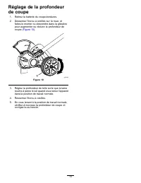
Adjusting the Depth of Cut 1. Remove the battery from the edger. 2. Loosen the wing nut on the wheel and move itup or down in the track to increase or decreasethe depth ( Figure 10 ). g333293 Figure 10 3. Adjust the depth so that the blade barely touchesthe ground when the machine is held in a norma...
Page 16 - Charging the Battery Pack
Charging the Battery Pack Important: The battery pack is not fully charged when you purchase it. Before using the tool forthe first time, place the battery pack in the chargerand charge it until the LED display indicates thebattery pack is fully charged. Read all safetyprecautions. Important: Charge...
Page 17 - Operating Tips
Operating Tips • Hold the edger with your right hand on the rearhandle and your left hand on the front handle. • Keep a firm grip with both hands while in operation. • The edger should be held at a comfortable positionwith the rear handle at about hip height. • The edger will edge along sidewalks, d...
Page 18 - Maintenance; Replacing the Blade; Replacing the Wheel
Maintenance After each use of the edger, complete the following: 1. Remove the battery from the edger. 2. Wipe the edger clean with a damp cloth. Do nothose the edger down or submerge it in water. 3. Wipe or scrape clean the cutting head area anytime there is an accumulation of debris. 4. Check and ...
Page 19 - Replacing the Skid Plate; Storage
6. Tighten the wing nut to secure the wheel. Replacing the Skid Plate If the skid plate becomes worn or damaged, replaceit; contact your authorized Toro distributor. 1. Ensure that the battery is removed from themachine. 2. Remove the 2 screws securing the skid plate tothe edger ( Figure 12 ). g3446...
Page 20 - Troubleshooting
Troubleshooting Perform only the steps described in these instructions. All further inspection, maintenance, and repair workmust be performed by an authorized service center or a similarly qualified specialist if you cannot solve theproblem yourself. Always remove the battery from the tool when trou...
Page 22 - California Proposition 65 Warning Information
California Proposition 65 Warning Information What is this warning? You may see a product for sale that has a warning label like the following: WARNING: Cancer and Reproductive Harm—www.p65Warnings.ca.gov. What is Prop 65? Prop 65 applies to any company operating in California, selling products in C...
Page 24 - ADVERTENCIA; Introducción
Si necesita ayuda, consultelos vídeos instruccionalesen www.Toro.com/supporto llame al 1-888-384-9939antes de devolver esteproducto. ADVERTENCIA CALIFORNIA Advertencia de la Propuesta 65 El cable eléctrico de este producto contiene plomo, que el Estado de California sabe que causa defectoscongénitos...
Page 25 - Seguridad; INSTRUCCIONES DE; Lea todas las instrucciones
Símbolo de alerta deseguridad El símbolo de alerta de seguridad ( Figura 2 ) que aparece en este manual y en la máquina identificamensajes de seguridad importantes que usted debeobservar para evitar accidentes. g000502 Figura 2 Símbolo de alerta de seguridad El símbolo de alerta de seguridad aparece...
Page 27 - IV. Mantenimiento y almacenamiento
IV. Mantenimiento y almacenamiento 1. No descuide el mantenimiento de la herramienta— debe estar siempre limpia y en buenascondiciones de uso para obtener el mejorrendimiento y para reducir el riesgo de lesiones.Siga las instrucciones al lubricar y cambiar deaccesorio. Mantenga las empuñaduras secas...
Page 28 - Pegatinas de seguridad e instrucciones
Pegatinas de seguridad e instrucciones Las pegatinas de seguridad e instrucciones están a la vista del operador y están ubicadascerca de cualquier zona de peligro potencial. Sustituya cualquier pegatina que esté dañada oque falte. decal144-3098 144-3098 decal144-3096 144-3096 decal144-3094 144-3094 ...
Page 30 - Montaje; Piezas sueltas; Despliegue de la empuñadura; Procedimiento
Montaje Piezas sueltas Utilice la tabla siguiente para verificar que no falta ninguna pieza. Procedimiento Descripción Cant. Uso 1 Llave Allen 1 Despliegue de la empuñadura. Empuñadura auxiliar 1 2 Herramienta de ajuste del cortabordes 1 Instalación de la empuñadura auxiliar. Importante: En el momen...
Page 32 - Instalación de la empuñadura auxiliar
2 Instalación de la empuñadura auxiliar Piezas necesarias en este paso: 1 Empuñadura auxiliar 1 Herramienta de ajuste del cortabordes Procedimiento 1. Separe la empuñadura auxiliar de la abrazadera retirando los 4 tornillos ( Figura 4 , A). 2. Alinee la empuñadura auxiliar con la abrazadera en el ma...
Page 33 - El producto; Especificaciones; Intervalos de temperatura adecuados; Accesorios
El producto g429628 Figura 5 1. Cierre de la batería 5. Protector 2. Botón de bloqueo 6. Zonas de ventilación 3. Empuñadura auxiliar 7. Cuchilla 4. Gatillo de accionamiento g330065 Figura 6 1. Cargador de bateríamodelo 88610 (incluidocon el modelo 51833) 2. Batería modelo 88620(incluida con el Model...
Page 34 - Operación; Arranque del cortabordes; Apagado del cortabordes
Operación Arranque del cortabordes 1. Alinee el hueco de la batería con la lengüeta delalojamiento de la empuñadura ( Figura 7 ). 2. Introduzca la batería en la empuñadura hasta labatería encaje en el cierre ( Figura 7 ). g333238 Figura 7 1. Cierre de la batería 3. Para arrancar el cortabordes, tire...
Page 36 - Carga de la batería
Carga de la batería Importante: En el momento de la compra la batería no está totalmente cargada. Antes de usarla herramienta por primera vez, coloque la bateríaen el cargador y cárguela hasta que el indicadorLED indique que la batería está completamentecargada. Lea todas las precauciones desegurida...
Page 37 - Consejos de operación
Consejos de operación • Sujete el cortabordes con la mano derecha sobrela empuñadura trasera y la mano izquierda en laempuñadura delantera. • Agarre firmemente con las dos manos mientrastrabaje. • Sujete el cortabordes en una posición cómoda,con la empuñadura trasera a la altura de lascaderas aproxi...
Page 38 - Mantenimiento; Sustitución de la cuchilla; Cambio de la rueda
Mantenimiento Después de cada uso del cortabordes, complete losprocedimientos siguientes: 1. Retire la batería del cortabordes. 2. Limpie el cortabordes pasando un trapohúmedo. No lave el cortabordes con unamanguera ni la sumerja en agua. 3. Limpie el cabezal de corte con un paño,rascando si es nece...
Page 39 - Cambio del patín
g334039 Figura 15 1. Ranura de profundidad decorte 5. Casquillos 2. Eje de la rueda 6. Arandela 3. Rueda 7. Tuerca de mariposa 4. Arandela de goma 3. Sustituya cualquier pieza que esté dañada o quefalte; póngase en contacto con su distribuidorautorizado Toro. 4. Introduzca el eje de la rueda a travé...
Page 40 - Almacenamiento
Almacenamiento Importante: Almacene la herramienta, la batería y el cargador solo a temperaturas queestén dentro del intervalo apropiado; consulte Especificaciones (página 11) . Importante: Si va a almacenar la batería fuera de temporada, retire la batería de la herramientay cargue la batería hasta ...
Page 41 - Solución de problemas
Solución de problemas Realice solo los pasos descritos en estas instrucciones. Cualquier otro trabajo de inspección, mantenimiento oreparación debe ser realizado por un Servicio Técnico Autorizado o por un especialista autorizado si nopuede solucionar el problema usted mismo. Retire siempre la bater...
Page 46 - ATTENTION
Si vous avez besoind'aide, visionnez lesvidéos d'instruction surwww.Toro.com/support ouappelez le 1-888-384-9939avant de renvoyer ceproduit. ATTENTION CALIFORNIE Proposition 65 - Avertissement Le cordon d'alimentation de cette machine contient du plomb, une substance chimique considérée par l'état d...
Page 47 - Sécurité; IMPORTANTES; Lire toutes les instructions
Symbole de sécurité Le symbole de sécurité ( Figure 2 ) utilisé dans ce manuel et sur la machine identifie d'importantsmessages de sécurité dont vous devez tenir comptepour éviter des accidents. g000502 Figure 2 Symbole de sécurité Le symbole de sécurité apparaît au-dessus de touteinformation signal...
Page 49 - IV. Entretien et remisage
IV. Entretien et remisage 1. Entretenez bien l'outil – gardez-le propre eten bon état pour assurer des performancesoptimales et réduire les risques de blessure.Suivez les instructions de graissage et deremplacement des accessoires. Gardez lespoignées propres et sèches, et exemptes d'huileet de grais...
Page 50 - Autocollants de sécurité et d'instruction
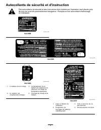
Autocollants de sécurité et d'instruction Des autocollants de sécurité et des instructions bien visibles par l'opérateur sont placés prèsde tous les endroits potentiellement dangereux. Remplacez tout autocollant endommagéou manquant. decal144-3098 144-3098 decal144-3096 144-3096 decal144-3094 144-30...
Page 52 - Mise en service; Pièces détachées; Procédure
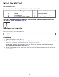
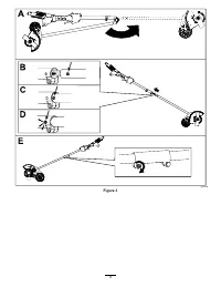
Mise en service Pièces détachées Reportez-vous au tableau ci-dessous pour vérifier si toutes les pièces ont été expédiées. Procédure Description Qté Utilisation 1 Clé Allen 1 Dépliage du manche. Poignée auxiliaire 1 2 Outil de réglage du coupe-bordures 1 Montage de la poignée auxiliaire. Important: ...
Page 54 - Montage de la poignée auxiliaire
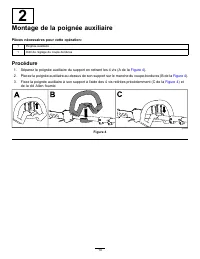
2 Montage de la poignée auxiliaire Pièces nécessaires pour cette opération: 1 Poignée auxiliaire 1 Outil de réglage du coupe-bordures Procédure 1. Séparez la poignée auxiliaire du support en retirant les 4 vis (A de la Figure 4 ). 2. Placez la poignée auxiliaire au-dessus de son support sur le manch...
Page 55 - Plages de température adéquates
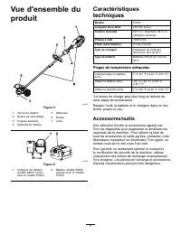
Vue d'ensemble duproduit g429628 Figure 5 1. Verrou de batterie 5. Déflecteur 2. Bouton de verrouillage 6. Évents 3. Poignée auxiliaire 7. Lame 4. Gâchette de marche g330065 Figure 6 1. Chargeur de batteriemodèle 88610 (inclusavec le modèle 51833) 2. Batterie modèle 88620(incluse avec le modèle51833...
Page 56 - Utilisation; Arrêt du coupe-bordures
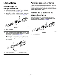
Utilisation Démarrage ducoupe-bordures 1. Alignez le creux de la batterie sur la languettedu corps de la poignée ( Figure 7 ). 2. Poussez la batterie dans le manche jusqu'à cequ'elle s'enclenche dans le verrou ( Figure 7 ). g333238 Figure 7 1. Verrou de batterie 3. Pour mettre le coupe-bordures en m...
Page 58 - Charge de la batterie
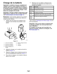
Charge de la batterie Important: La batterie n'est pas complètement chargée à l'achat. Avant d'utiliser l'outil pour lapremière fois, placez la batterie dans le chargeuret chargez-la jusqu'à ce que les diodes indiquentque la batterie est complètement chargée. Liseztoutes les consignes de sécurité. I...
Page 59 - Conseils d'utilisation
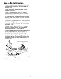
Conseils d'utilisation • Tenez le coupe-bordures en posant la main droitesur la poignée arrière et la main gauche sur lapoignée avant. • Tenez fermement l'appareil des deux mainspendant l'utilisation. • Tenez le coupe-bordures dans une positionconfortable, avec la poignée arrière à peu prèsà hauteur...
Page 60 - Entretien; Remplacement de la lame; Remplacement de la roue
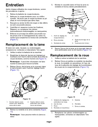
Entretien Après chaque utilisation du coupe-bordures, suivezles procédures ci-après : 1. Retirez la batterie du coupe-bordures. 2. Nettoyez le coupe-bordures avec un chiffonhumide. Ne lavez pas le coupe-bordures au jetd'eau et ne le trempez pas dans l'eau. 3. Essuyez ou raclez la tête de coupe si de...
Page 61 - Remisage
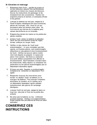
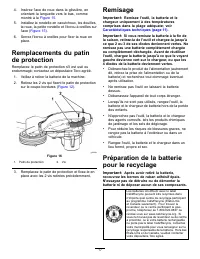
4. Insérez l'axe de roue dans la glissière, enorientant la languette vers le bas, commemontré à la Figure 15 . 5. Installez la rondelle en caoutchouc, les douilles,la roue, la petite rondelle et l'écrou à oreilles surl'axe ( Figure 15 ). 6. Serrez l'écrou à oreilles pour fixer la roue enplace. Rempl...
Page 62 - Dépistage des défauts
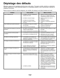
Dépistage des défauts Effectuez uniquement les opérations décrites dans cette notice. Tout autre contrôle, entretien ou réparationdoit être réalisé par un centre d'entretien agréé ou un spécialiste qualifié si vous n'arrivez pas à résoudre leproblème vous-même. Retirez toujours la batterie avant de ...
Page 64 - Cancer et troubles de la reproduction –
Proposition 65 de Californie – Information concernant cet avertissement En quoi consiste cet avertissement? Certains produits commercialisés présentent une étiquette d'avertissement semblable à ce qui suit : AVERTISSEMENT : Cancer et troubles de la reproduction – www.p65Warnings.ca.gov. Qu’est-ce qu...