Page 2 - Instructions; RISK OF INJURY
Instructions 60 1 Instructions 1.1 General safety instructions • Protect your hands by wearing oven gloves when moving food inside the oven. • Never try to put out a fire or flames with water: turn off the appliance and smother the flames with a fire blanket or other appropriate cover. • This applia...
Page 4 - RISK OF DAMAGING THE
Instructions 62 • Use wooden or plastic utensils.• Racks and trays should be inserted as far as they will go into the side guides. The mechanical safety locks that prevent them from being removed must face downwards and towards the back of the oven cavity. • Do not sit on the appliance.• Do not use ...
Page 6 - Installation and maintenance; MUST NOT
Instructions 64 Installation and maintenance • THIS APPLIANCE MUST NOT BE INSTALLED IN A BOAT OR CARAVAN. • The appliance must not be installed on a pedestal. • Position the appliance into the cabinet cut-out with the help of a second person. • To prevent any possible overheating, the appliance shou...
Page 7 - For this appliance; Manufacturer’s liability
Instructions 65 EN • This appliance is not connected to an exhaust system for combustion products. It must be installed and connected in compliance with the current installation regulations. Special attention should be paid to the relevant requirements as for ventilation. For this appliance • Ensure...
Page 8 - Power voltage
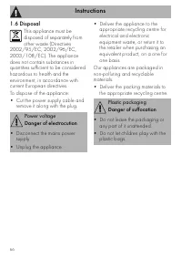
Instructions 66 1.6 Disposal This appliance must be disposed of separately from other waste (Directives 2002/95/EC, 2002/96/EC, 2003/108/EC). The appliance does not contain substances in quantities sufficient to be considered hazardous to health and the environment, in accordance with current Europe...
Page 9 - How to read the user manual
Instructions 67 EN 1.7 How to read the user manual This user manual uses the following reading conventions: 1.8 To save energy • Only preheat the appliance if the recipe requires you to do so. • Unless otherwise indicated on the package, defrost frozen foods before placing them in the oven. • When c...
Page 10 - Description; General Description
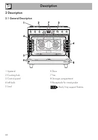
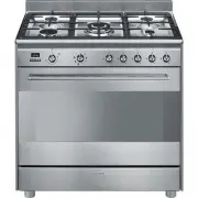
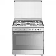
Description 68 2 Description 2.1 General Description 1 Upstand 2 Cooking hob 3 Control panel 4 Left bulb 5 Seal 6 Door 7 Fan 8 Storage compartment 9 Receptacle for meat probe Rack/tray support frames
Page 11 - AUX
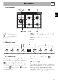
Description 69 EN 2.2 Cooking hob AUX = Auxiliary burner SR = Semi-rapid burner R = Rapid burner UR2 int. = Ultra rapid burner with internal crown UR2 ext. = external crown ultra rapid burner 2.3 Control panel 1 Hob burner knobs For lighting and adjusting the hob burners.Press and turn the knobs ant...
Page 12 - from the
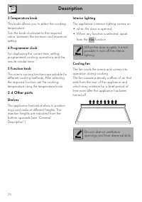
Description 70 3 Temperature knob This knob allows you to select the cooking temperature.Turn the knob clockwise to the required value, between the minimum and maximum setting. 4 Programmer clock For displaying the current time, setting programmed cooking operations and the minute minder timer. 5 Fu...
Page 13 - Available accessories; Rack
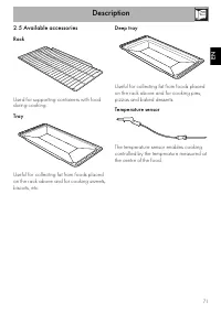
Description 71 EN 2.5 Available accessories Rack Used for supporting containers with food during cooking. Tray Useful for collecting fat from foods placed on the rack above and for cooking sweets, biscuits, etc. Deep tray Useful for collecting fat from foods placed on the rack above and for cooking ...
Page 14 - Protective cover
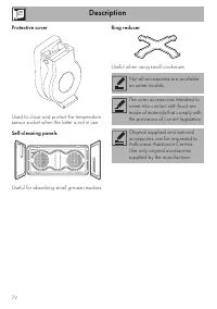
Description 72 Protective cover Used to close and protect the temperature sensor socket when the latter is not in use. Self-cleaning panels Useful for absorbing small grease residues. Ring reducer Useful when using small cookware. Not all accessories are available on some models. The oven accessorie...
Page 15 - Use
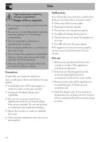
Use 73 EN 3 Use Instructions High temperature inside the oven during use Danger of burns • Keep the oven door closed during cooking. • Protect your hands wearing heat resistant gloves when moving food inside the oven. • Do not touch the heating elements inside the oven. • Do not pour water directly ...
Page 16 - Precautions
Use 74 Precautions A gas leak can cause an explosion.If you smell gas or there are faults in the gas system:• Immediately turn off the gas supply or close the valve on the gas cylinder. • Extinguish all naked flames and cigarettes. • Do not turn on power switches or appliances and do not remove plug...
Page 17 - Using the accessories; Ring reducers
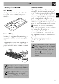
Use 75 EN 3.1 Using the accessories Ring reducers The ring reducers must be placed on the hob grids. Make sure they are placed properly. Racks and trays Racks and trays have to be inserted into the side guides until they come to a complete stop. The mechanical safety locks that prevent the rack from...
Page 18 - Practical tips for using the hob; Using the storage compartment
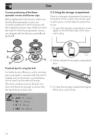
Use 76 Correct positioning of the flame-spreader crowns and burner caps Before lighting the hob burners, make sure that the flame-spreader crowns are correctly positioned in their housings with their respective burner caps. Make sure that the holes 1 of the flame-spreader crowns are aligned with the...
Page 19 - Switching on the oven
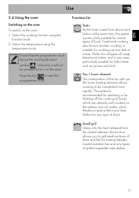
Use 77 EN 3.4 Using the oven Switching on the oven To switch on the oven:1. Select the cooking function using the function knob. 2. Select the temperature using the temperature knob. Functions list Ensure that the programmer clock shows the cooking duration symbol , otherwise it will not be possible...
Page 20 - Grill
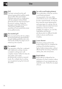
Use 78 Grill The heat coming from the grill element gives perfect grilling results above all for thin and medium thickness meat and, in combination with the rotisserie (where fitted), gives the food an even browning at the end of cooking. Perfect for sausages, spare ribs and bacon. This function ena...
Page 21 - Eco
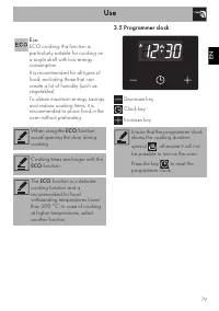
Use 79 EN 3.5 Programmer clock Decrease key Clock key Increase key Eco ECO cooking: this function is particularly suitable for cooking on a single shelf with low energy consumption.It is recommended for all types of food, excluding those that can create a lot of humidity (such as vegetables).To obta...
Page 22 - Setting the time
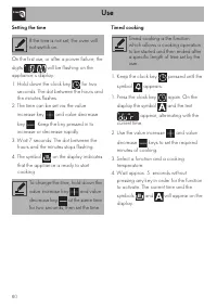
Use 80 Setting the time On the first use, or after a power failure, the digits will be flashing on the appliance’s display. 1. Hold down the clock key for two seconds. The dot between the hours and the minutes flashes. 2. The time can be set via the value increase key and value decrease key . Keep t...
Page 23 - Programmed cooking
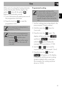
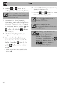
Use 81 EN At the end of cooking the heating elements will be deactivated. On the display, the symbol turns off, the symbol flashes and the buzzer sounds.5. To turn the buzzer off, simply press one of the programmer clock keys. 6. Press the clock key to reset the programmer clock. Programmed cooking ...
Page 25 - Minute minder timer
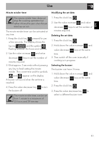
Use 83 EN Minute minder timer The minute minder timer can be activated at any time. 1. Keep the clock key pressed for per a few seconds. The display shows the figures and the symbol flashing between the hours and minutes. 2. Use the value increase and value decrease keys to set the number of minutes...
Page 26 - Using the temperature probe; Danger of burns
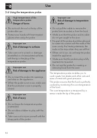
Use 84 3.6 Using the temperature probe The temperature probe enables you to cook roasts, loin steaks and other cuts and sizes of meat with great precision.The probe ensures that the food is perfectly cooked by monitoring the core temperature of the food.The core temperature is measured by a sensor i...
Page 27 - Positioning the probe
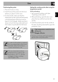
Use 85 EN Positioning the probe 1. Place the food on a tray.2. Insert the tip of the probe into the food before you place it in the oven. 3. For best results, make sure that the temperature probe is placed transversely in the thickest part of the food and for least 3/4 of its length. Make sure that ...
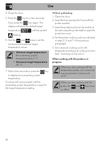
Page 28 - Minimum target temperature:
Use 86 4. Close the door. 5. Press the key for a few seconds; Now press the key again. The display will show the default target temperature with the symbol flashing. 6. Use the and keys to set the minimum and maximum target temperature values. 7. Wait a few seconds or press the key to display the mo...
Page 29 - At the end of cooking
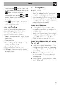
Use 87 EN 1. Hold down the key for a long time to enable the minute minder timer; press again to display the target temperature, and use the and keys to adjust it while cooking is in progress. 2. Press again or wait 5 seconds to return to cooking mode. At the end of cooking When the temperature prob...
Page 30 - Advice for defrosting and proving
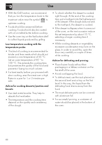
Use 88 • With the Grill function, we recommend that you turn the temperature knob to the maximum value near the symbol to optimise cooking. • Foods should be seasoned before cooking. Foods should also be coated with oil or melted butter before cooking. • Use the oven tray on the first bottom shelf t...
Page 31 - Cooking information table
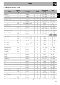
Use 89 EN Cooking information table Food Weight (kg) Function Shelf Temperature (°C) Time (minutes) Lasagne 3 - 4 Static 1 220 - 230 45 - 50 Pasta bake 3 - 4 Static 1 220 - 230 45 - 50 Roasted veal 2 Round 2 180 - 190 90 - 100 Pork loin 2 Round 2 180 - 190 70 - 80 Sausages 1.5 Fan-assisted grill 4 2...
Page 32 - Illustrative table of temperature probe cooking cycle settings; Type and cut of meat
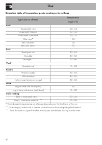
Use 90 Illustrative table of temperature probe cooking cycle settings Type and cut of meat Temperature target (°C) Beef Roast beef: rare 50 - 53 Roast beef: medium 55 - 58 Roast beef: well done 65 - 70 Ribs: rare* 50 Ribs: medium* 58 Ribs: well done* 70 Pork Roast pork loin 80 - 85 Shoulder 80 - 85 ...
Page 33 - Cleaning and maintenance
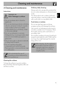
Cleaning and maintenance 91 EN 4 Cleaning and maintenance Instructions Cleaning the surfaces To keep the surfaces in good condition, they should be cleaned regularly after use. Let them cool first. Ordinary daily cleaning Always and only use specific products that do not contain abrasives or chlorin...
Page 34 - Cooking hob grids
Cleaning and maintenance 92 4.1 Cleaning the hob Cooking hob grids Remove the grids and clean them in lukewarm water and non-abrasive detergent. Make sure to remove any encrustations. Dry them thoroughly and return them to the hob. Flame-spreader crowns and burner caps For easier cleaning, the flame...
Page 35 - Cleaning the door; Removing the door
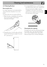
Cleaning and maintenance 93 EN 4.2 Cleaning the door Removing the door For easier cleaning it is recommended to remove the door and place it on a tea towel.To remove the door proceed as follows:1. Open the door completely and insert two pins into the holes on the hinges indicated in the figure. 2. G...
Page 36 - Removing the internal glass panes
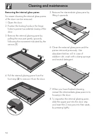
Cleaning and maintenance 94 Removing the internal glass panes For easier cleaning the internal glass panes of the door can be removed.1. Open the door.2. Position the locking hooks in the hinge holes to prevent accidental closing of the door. 3. Remove the internal glazing pane by pulling the rear p...
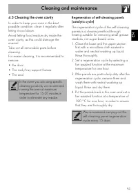
Page 37 - Cleaning the oven cavity; Set a regeneration cycle by selecting a
Cleaning and maintenance 95 EN 4.3 Cleaning the oven cavity In order to keep your oven in the best possible condition, clean it regularly after letting it cool down.Avoid letting food residue dry inside the oven cavity, as this could damage the enamel.Take out all removable parts before cleaning.For...
Page 38 - Preliminary operations
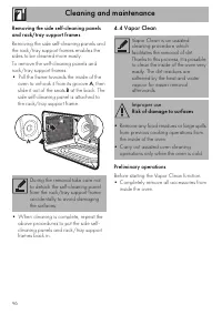
Cleaning and maintenance 96 Removing the side self-cleaning panels and rack/tray support frames Removing the side self-cleaning panels and the rack/tray support frames enables the sides to be cleaned more easily.To remove the self-cleaning panels and rack/tray support frames:• Pull the frame towards...
Page 39 - Vapor Clean setting
Cleaning and maintenance 97 EN • Pour approximately 40 cc of water into the tray. Make sure it does not overflow out of the cavity. • Spray a water and washing up liquid solution inside the oven using a spray nozzle. Direct the spray against the side walls, upwards, downwards and towards the deflect...
Page 40 - End of the Vapor Clean cycle; Extraordinary maintenance; Installing and removing the seal
Cleaning and maintenance 98 End of the Vapor Clean cycle 4. Open the door and wipe away the less stubborn dirt with a microfibre cloth. 5. Use an anti-scratch sponge with brass filaments on tougher encrustations. 6. In case of grease residues use specific oven cleaning products. 7. Remove the water ...
Page 41 - Replacing the internal light bulb
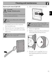
Cleaning and maintenance 99 EN Replacing the internal light bulb 1. Completely remove all accessories from inside the oven. 2. Remove the rack/tray support frames. 3. Use a tool (e.g. a spoon) to remove the bulb cover. 4. Slide out and remove the light bulb. 5. Fit the new light bulb. 6. Refit the c...
Page 42 - Installation; General information
Installation 100 5 Installation 5.1 Gas connection General information Connection to the gas mains can be made using a continuous wall steel hose in compliance with the guidelines established by the standards in force. The appliance is preset for natural gas G20 (2H) at a pressure of 20 mbar. For su...
Page 43 - Connection with a steel hose
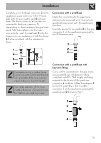
Installation 101 EN Carefully screw the hose connector 3 to the appliance’s gas connector 1 (½” thread ISO 228-1), placing the seal 2 between them. The hose connector 4 can also be screwed to the hose connector 3 , depending on the diameter of the gas hose used. After having tightened the hose conne...
Page 44 - Connection to LPG
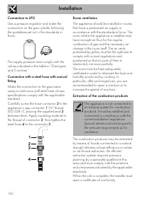
Installation 102 Connection to LPG Use a pressure regulator and make the connection on the gas cylinder following the guidelines set out in the standards in force. The supply pressure must comply with the values indicated in the table in “Gas types and Countries”. Connection with a steel hose with c...
Page 45 - Adaptation to different types of; Replacing nozzles
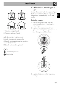
Installation 103 EN 1 Extraction using a hood 2 Extraction without a hood A Single natural draught chimney B Single chimney with extractor fan C Directly outdoors with wall- or window- mounted extractor fan D Directly outdoors through wall Air Combustion products Extractor fan 5.2 Adaptation to diff...
Page 46 - Adjusting the minimum setting for LPG
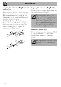
Installation 104 Adjusting the minimum setting for natural or town gas Light the burner and turn it to the minimum position. Extract the gas cock knob and turn the adjustment screw next to the tap rod (depending on the model) until the correct minimum flame is achieved.Refit the knob and verify that...
Page 47 - Gas types and Countries; SE RU DK PL HU
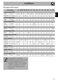
Installation 105 EN Gas types and Countries Gas types IT GB-IE FR-BE DE AT NL ES PT SE RU DK PL HU 1 Natural gas G20 G20 20 mbar • • • • • • • • • • G20/25 20/25 mbar • 2 Natural gas G20 G20 25 mbar • 3 Natural gas G25 G25 25 mbar • G25.3 25 mbar • 4 Natural gas G25.1 G25.1 25 mbar • 5 Natural gas G...
Page 48 - Burner and nozzle characteristics tables
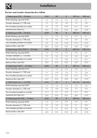
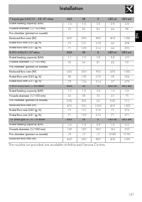
Installation 106 Burner and nozzle characteristics tables 1 Natural gas G20 – 20 mbar AUX SR R UR2 int. UR2 ext. Rated heating capacity (kW) 1.0 1.8 3.0 0.9 4.1 Nozzle diameter (1/100 mm) 72 97 120 70 150 Pre-chamber (printed on nozzle) (X) (Z) (H9) (H1) (H3) Reduced flow rate (W) 400 500 800 400 12...
Page 50 - Heavy appliance
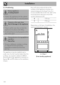
Installation 108 5.3 Positioning This appliance may be installed next to walls, one of which must be higher than the worktop, at a minimum distance of X mm from the side of the appliance, as shown in figures " A " and " C " relative to the installation classes. Any wall units positio...
Page 51 - B - Class 2 subclass 1; Appliance overall dimensions
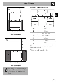
Installation 109 EN B - Class 2 subclass 1 (Built-in appliance) C - Class 2 subclass 1 (Built-in appliance) Appliance overall dimensions 1 Minimum distance from side walls or other flammable material. 2 Minimum cabinet width ( =A ). The appliance must be installed by a qualified technician and accor...
Page 52 - Electrical connection
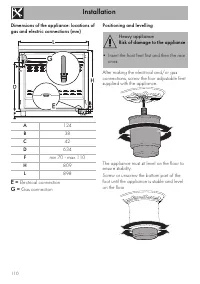
Installation 110 Dimensions of the appliance: locations of gas and electric connections (mm) E = Electrical connection G = Gas connection Positioning and levelling After making the electrical and/or gas connections, screw the four adjustable feet supplied with the appliance. The appliance must sit l...
Page 53 - Fastening to the wall
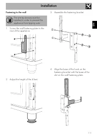
Installation 111 EN Fastening to the wall 1. Screw the wall fastening plate to the rear of the appliance. 2. Adjust the height of the 4 feet. 3. Assemble the fastening bracket. 4. Align the base of the hook on the fastening bracket with the base of the slot on the wall fastening plate. The anti-tip ...
Page 54 - Align the base of the fastening bracket
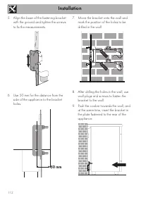
Installation 112 5. Align the base of the fastening bracket with the ground and tighten the screws to fix the measurements. 6. Use 50 mm for the distance from the side of the appliance to the bracket holes. 7. Move the bracket onto the wall and mark the position of the holes to be drilled in the wal...
Page 55 - Assembling the upstand; Electrical connection
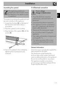
Installation 113 EN Assembling the upstand The upstand must always be positioned and secured correctly on the appliance.1. Loosen the 4 screws ( A ) on the back of the hob (2 for each side) using a screwdriver. 2. Place the upstand on the worktop. 3. Align the slots of the upstand ( B ) with the scr...
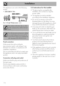
Page 56 - Fixed connection; Instructions for the installer
Installation 114 The appliance can work in the following modes:• 220-240 V 1N ~ 3 x 1.5 mm² three-core cable. Fixed connection Fit the power line with an all-pole disconnection switch, with at least 3 mm between its contacts, in compliance with installation regulations.The circuit breaker should be ...