Page 2 - Save all warnings and instructions for future reference.; WORK AREA SAFETY; Keep work area clean and well lit.; ELECTRICAL SAFETY; Do not expose power tools to rain or wet conditions.; PERSONAL SAFETY; Dress properly. Do not wear loose clothing or; POWER TOOL USE AND CARE; GENERAL SAFETY RULES
2 - English WARNING: Read all safety warnings, instructions, illustrations and specifications provided with this power tool. Failure to follow all instructions listed below may result in electric shock, fire and/or serious injury. Save all warnings and instructions for future reference. The term “po...
Page 3 - Keep cutting tools sharp and clean.; BATTERY TOOL USE AND CARE; Use battery only with charger listed.; SERVICE
3 - English GENERAL SAFETY RULES Disconnect the plug from the power source and/or remove the battery pack, if detachable, from the power tool before making any adjustments, changing accessories, or storing power tools. Such preventive safety measures reduce the risk of starting the power tool acci...
Page 4 - TABLE SAW SAFETY RULES; GUARDING RELATED WARNINGS
4 - English TABLE SAW SAFETY RULES GUARDING RELATED WARNINGS Keep guards in place. Guards must be in working order and be properly mounted. A guard that is loose, damaged, or is not functioning correctly must be repaired or replaced. Always use saw blade guard, riving knife and anti- kickback pa...
Page 5 - KICKBACK CAUSES AND RELATED WARNINGS
5 - English TABLE SAW SAFETY RULES KICKBACK CAUSES AND RELATED WARNINGS Kickback is a sudden reaction of the workpiece due to a pinched, jammed saw blade or misaligned line of cut in the workpiece with respect to the saw blade or when a part of the workpiece binds between the saw blade and the rip f...
Page 6 - ADDITIONAL SAFETY RULES
6 - English ADDITIONAL SAFETY RULES Know your power tool. Read the operator’s manual carefully. Learn the saw’s applications and limitations as well as the specific potential hazards related to this tool. Make workshop childproof with padlocks and master switches, or by removing starter keys. ...
Page 7 - SYMBOLS
7 - English SYMBOLS Some of the following symbols may be used on this tool. Please study them and learn their meaning. Proper interpretation of these symbols will allow you to operate the tool better and safer. SYMBOL NAME DESIGNATION/EXPLANATION Safety Alert Indicates a potential personal injury ha...
Page 8 - GLOSSARY OF TERMS
8 - English GLOSSARY OF TERMS Pilot Hole (drill presses and scroll saws) A small hole drilled in a workpiece that serves as a guide for drilling large holes accurately or for insertion of a scroll saw blade. Push Blocks (jointer planers) Device used to feed the workpiece over the jointer planer cutt...
Page 9 - FEATURES; PRODUCT SPECIFICATIONS; KNOW YOUR TABLE SAW; ACCESSORY STORAGE; BEVEL LOCKING LEVER
9 - English FEATURES PRODUCT SPECIFICATIONS Blade Arbor .............................................................. 5/8 in.Blade Diameter ......................................................8-1/4 in.Blade Tilt ................................................................. 0˚ - 45˚ Input .......
Page 11 - RIVING KNIFE; OPERATING COMPONENTS; SWITCH ASSEMBLY; ALWAYS
11 - English FEATURES RIVING KNIFE - A removable metal piece of the blade guard assembly with kickback pawls, slightly thinner than the saw blade, which helps keep the kerf open and prevent kickback. When in the through sawing, or “up” position, it is higher than the saw blade. When in the non-throu...
Page 12 - TOOLS NEEDED
12 - English The following tools (not included or drawn to scale) are needed for assembly and making adjustments: TOOLS NEEDED Fig. 5 FRAMING SQUARE PHILLIPS SCREWDRIVER FLATHEAD SCREWDRIVER SOCKET WRENCH AND SOCKETS (8 mm and 13 mm) COMBINATION SQUARE C-CLAMPS 13mm WRENCH
Page 13 - LOOSE PARTS
LOOSE PARTS 13 - English The following items are included with your table saw: Fig. 6 A. Blade Guard with Anti-kickback Pawls.................... 1 B. Handle Assembly ..................................................... 1 C. Handle End Cap ....................................................... 1 D...
Page 14 - UNPACKING; ASSEMBLY
14 - English UNPACKING This product requires assembly. Carefully lift saw from the carton and place it on a level work surface. NOTE: This tool is heavy. To avoid back injury, keep your knees bent and lift with your legs, not your back, and get help when needed. WARNING: Do not use this product if...
Page 15 - MOUNTING HOLES
15 - English ASSEMBLY MOUNTING HOLES See Figure 7. The table saw must be mounted to a firm supporting surface such as a workbench or leg stand. Four bolt holes have been provided in the saw’s base for this purpose. To mount the saw to a work bench, insert bolts that are of sufficient length to accom...
Page 16 - CHANGING RIVING KNIFE POSITIONS; To place in the “up” position for all through cutting:; To place in the “down” position for all non-through cutting:
16 - English ASSEMBLY CHANGING RIVING KNIFE POSITIONS See Figure 10. This saw is shipped with a riving knife that should be placed in the “down” position for non-through cutting and must be placed in the “up” position for all other cutting operations. CAUTION: Use caution when reaching inside the th...
Page 17 - CHECKING SAW BLADE INSTALLATION; To tighten the blade:
17 - English ASSEMBLY CHECKING SAW BLADE INSTALLATION See Figure 11. NOTICE: To work properly, the saw blade teeth must point down toward the front of the saw. Failure to heed this warning could cause damage to the saw blade, the saw, or the workpiece. Remove the battery. Remove the blade wrench...
Page 18 - INSTALLING THE BLADE GUARD; To install blade guard:
18 - English ASSEMBLY INSTALLING THE BLADE GUARD See Figures 12 - 13. WARNING: Always install the blade guard onto the riving knife in the “up” position to provide proper blade coverage. Installing the guarding components onto the riving knife in any oth-er position will prevent them from working as...
Page 19 - To check alignment of the riving knife:
19 - English Fig. 14 ASSEMBLY TO CHECK AND ALIGN THE RIVING KNIFEAND SAW BLADE See Figures 14 - 15. To check alignment of the riving knife: Remove the battery. Raise the saw blade by turning the height/bevel adjusting handwheel clockwise. Adjust the bevel angle to 0° and lock the bevel locking...
Page 20 - STORING TABLE SAW ACCESSORIES
20 - English Fig. 17 ASSEMBLY RIP FENCE STORING TABLE SAW ACCESSORIES See Figures 16 - 19. When not in use the rip fence, riving knife, wrenches, blade guard, miter gauge, and push stick may be stored beneath the saw table. Fig. 19 Fig. 18 Fig. 16 RIP FENCE STORAGE BLADE GUARD BLADE WRENCHES RIVING ...
Page 21 - INSTALLING/REMOVING THE BATTERY PACK; OPERATION; APPLICATIONS; BATTERY PORT
21 - English INSTALLING/REMOVING THE BATTERY PACK See Figure 20. Place battery pack in the saw. Align raised rib on battery pack with groove inside saw. Make sure the latches on each side of the battery pack snap in place and that the battery pack is secured in the tool before beginning operat...
Page 22 - CAUSES OF KICKBACK
22 - English OPERATION CAUSES OF KICKBACK Kickback can occur when the blade stalls or binds, kicking the workpiece back toward you with great force and speed. If your hands are near the saw blade, they may be jerked loose from the workpiece and may contact the blade. Obviously, kickback can cause se...
Page 23 - CUTTING AIDS; To make a push stick:; To make a push block:
23 - English Fig. 22 PUSH BLOCKS HANDLE BASE PUSH STICKS PUSH STICK PUSH BLOCK Fig. 21 GRIP NOTCH CUTTING AIDS See Figures 21 - 22. Push sticks are devices that may be used for pushing a workpiece through the blade in any rip cut. When making non-through cuts or ripping narrow stock, always use a pu...
Page 24 - WORKPIECE SUPPORTS; To attach the auxiliary fence to the rip fence:
24 - English OPERATION 3/4 in. 21 in. 3 1/2 in. WORKPIECE SUPPORTS See Figure 23. When cutting with your table saw, make sure that the workpiece you are cutting is properly supported. Properly supporting the workpiece throughout the cutting process not only improves the accuracy of the cut but also ...
Page 25 - OFF; HOW TO MOUNT A FEATHERBOARD; Making a Rip Cut; FEATHERBOARD
25 - English Prepare the saw for ripping as discussed on page 32. Set the rip fence to allow approximately a 1/4 in. “finger” to be cut in the stock. Feed the stock only to the mark previously made at 4 in. Turn the saw OFF and allow the blade to completely stop rotating before removing the stock. R...
Page 26 - BEVEL RIP CUT; Do not; TYPES OF CUTS
26 - English OPERATION BEVEL RIP CUT RIP CUT CROSS CUT MITER CUT COMPOUND (BEVEL) MITER CUT BEVEL CROSS CUT 1 WARNING: The featherboard must be installed in front of the blade. Do not locate the featherboard to the rear of the blade. Kickback can result from the featherboard pinching the workpiece a...
Page 27 - TO CHANGE BLADE DEPTH
27 - English OPERATION The kerf (the cut made by the blade in the wood) will be wider than the blade to avoid overheating or binding. Make allowance for the kerf when measuring wood. Make sure the kerf is made on the waste side of the measuring line. Cut the wood with the finish side up. Kno...
Page 28 - TO USE THE RIP FENCE; NEVER; To Check the Alignment
28 - English OPERATION Fig. 34 Fig. 33 Fig. 32 LOW FENCE RIP FENCE TO USE THE RIP FENCE See Figures 32 and 33. WARNING: To reduce the risk of injury, always make sure the rip fence is parallel to the blade before beginning any operation. NOTE: The rip fence included with your saw has a low fence. Th...
Page 29 - TO USE THE MITER GAUGE; Cleaning the Riving Knife Lock Lever Plates; If the distances are different:
29 - English Remove the battery. Loosen the rip fence by lifting the locking lever. Using a framing square, set the rip fence 2 in. from the blade tip edge. Loosen the screw on the scale indicator and align with the 2 in. mark as shown. Tighten the screw and check the dimension and the rip...
Page 30 - MAKING CUTS
30 - English NOTE: The bolts are located above the height/bevel adjusting handwheel and under the saw table in the front of the saw. Turn adjusting bolt left or right until the blade is square. Tighten the locking bolts. Check again for squareness and continue to adjust if needed. WARNING: To re...
Page 31 - MAKING A CROSS CUT; To make repetitive cross cuts:
31 - English OPERATION MAKING A CROSS CUT See Figures 39 - 41. WARNING: Make sure the blade guard assembly with kickback pawls is installed and working properly to avoid serious possible injury. WARNING: Using the rip fence as a cutoff gauge when cross cutting will result in kickback which can cause...
Page 32 - MAKING A RIP CUT
32 - English OPERATION REPETITIVE CROSS CUT Fig. 41 STOP BLOCK Remove the rip fence. Set the blade to the correct depth for the workpiece. Set the miter gauge to 0° and tighten the lock knob. Position a 3 in. block of wood at the desired distance from the blade to act as a cut-off gauge. S...
Page 33 - How To Make A Jig (For Rip Cutting Narrow
33 - English Using a push stick and/or push blocks, slowly feed the workpiece toward the blade. Stand slightly to the side of the workpiece as it contacts the blade to reduce the chance of injury should kickback occur. Once the blade has made contact with the workpiece, use the hand closest to t...
Page 35 - MAKING A BEVEL RIP CUT
35 - English Fig. 47 BEVEL RIP CUT RIP FENCE SCALE BLADE ANGLED When the cut is made, turn the saw off. Wait for the blade to come to a complete stop before removing the workpiece. MAKING A BEVEL RIP CUT See Figure 47. WARNING: Make sure the blade guard assembly with kickback pawls is installed an...
Page 36 - MAKING A LARGE PANEL CUT; LARGE PANEL CUT
36 - English Adjust the bevel angle to the desired setting. Lock the bevel locking lever. Set the blade to the correct depth for the workpiece. Set the miter gauge to the desired angle and tighten the lock knob. Make sure the wood is clear of the blade before turning on the saw. Insert t...
Page 37 - MAKING A NON-THROUGH CUT; DO NOT; Making a
37 - English When the cut is made, turn the saw off. Wait for the blade to come to a complete stop before removing the workpiece. MAKING A NON-THROUGH CUT See Figure 50. WARNING: DO NOT install dado blades on this machine. The arbor shaft has insufficient threads to mount a dado blade. Mounting a ...
Page 38 - REPLACING THE BLADE; To install a standard blade:; ADJUSTMENTS
38 - English WARNING: Before performing any adjustment, make sure the battery is removed and the top button on the switch is not depressed. Failure to heed this warning could result in serious personal injury. To avoid unnecessary set-ups and adjustments, a good practice is to check your setups care...
Page 39 - To Set the; TO SET THE BLADE AT 0° AND 45°; If the blade is not an exact 45°:
39 - English ADJUSTMENTS After installation, adjust the rip scale indicator to account for the kerf and thickness of the blade. Refer to To Set the Rip Fence Scale Indicator to the Blade in the Operation section of this manual. In cutting operations, the scale will be set to the side of the blade wh...
Page 40 - Once blade is 45° to the table:
40 - English ADJUSTMENTS Repeat above steps to readjust and recheck blade angle as needed. Once blade is 45° to the table: Check bevel indicator. If indicator is not pointing to the 45º mark on the bevel scale, loosen the indicator adjusting screw and adjust indicator. Retighten screws. When...
Page 41 - GENERAL MAINTENANCE; do not; MAINTENANCE; LUBRICATION; LOCK
41 - English WARNING: When servicing, use only identical replacement parts. Use of any other parts may create a hazard or cause product damage. WARNING: Always wear eye protection with side shields marked to comply with ANSI Z87.1 during product operation. If operation is dusty, also wear a dust mas...
Page 42 - DUST; DUST CHUTE; To clean the dust chute:; TROUBLESHOOTING; PROBLEM
42 - English MAINTENANCE Fig. 59 DUST CHUTE SCREW DUST CHUTE See Figure 59. This saw features a dust chute for convenience in discharging sawdust. A standard shop vac can be attached to the chute, located under the back side of the saw.During periods of extended use, the dust chute should be emptied...
Page 43 - Adjusting the Blade Parallel to the
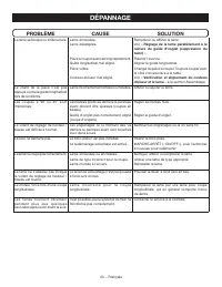
43 - English TROUBLESHOOTING PROBLEM CAUSE SOLUTION Cutting binds or burns work. Blade is dull.Blade is heeling. Work is fed too fast.Rip fence is misaligned.Workpiece is warped. Riving knife is out of alignment. Replace or sharpen blade.See Adjusting the Blade Parallel to the Miter Gauge Groove (Re...
Page 44 - SÉCURITÉ DU LIEU DE TRAVAIL; Garder le lieu de travail propre et bien éclairé.; SÉCURITÉ ÉLECTRIQUE; RÈGLES DE SÉCURITÉ GÉNÉRALES
2 − Français AVERTISSEMENT : Lire les avertissements de sécurité, les instructions et les précisions et consulter les illustrations fournis avec cet outil électrique. Le fait de ne pas se conformer à l’ensemble des consignes présentées ci-dessous risque d’entraîner des décharges électriques, un ince...
Page 45 - Garder les outils bien affûtés et propres.; UTILISATION ET ENTRETIEN DE LA PILE; Ne recharger les piles qu’avec l’appareil indiqué.; DÉPANNAGE
3 − Français RÈGLES DE SÉCURITÉ GÉNÉRALES Ne pas utiliser l’outil si le commutateur ne permet pas de le mettre en marche ou de l’arrêter. Tout outil qui ne peut pas être contrôlé par son commutateur est dangereux et doit être réparé. Avant de procéder à un réglage, à un changement d’accessoire o...
Page 46 - RÈGLES DE SÉCURITÉ SCIE À TABLE; AVERTISSEMENTS LIÉS AUX PROTECTEURS
4 − Français RÈGLES DE SÉCURITÉ SCIE À TABLE AVERTISSEMENTS LIÉS AUX PROTECTEURS Laisser les protecteurs en place. Les protecteurs doivent être en bon état de marche et être bien installés. Un protecteur lâche, endommagé ou qui ne fonctionne pas correctement doit être réparé ou remplacé. Toujour...
Page 48 - RÈGLES DE SÉCURITÉ SUPPLÉMENTAIRES
6 − Français RÈGLES DE SÉCURITÉ SUPPLÉMENTAIRES Veiller à bien connaître l’outil. Lire attentivement le manuel d’utilisation. Apprendre les applications et les limites de la scie, ainsi que les risques spécifiques relatifs à son utilisation. Assurer la sécurité des enfants en installant des cade...
Page 49 - SYMBOLES
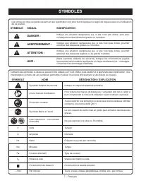
7 − Français SYMBOLES Certains des symboles ci-dessous peuvent être utilisés sur l’outil. Veiller à les étudier et à apprendre leur signification. Une interprétation correcte de ces symboles permettra d’utiliser l’outil plus efficacement et de réduire les risques. SYMBOLE NOM DÉSIGNATION / EXPLICATI...
Page 50 - GLOSSAIRE
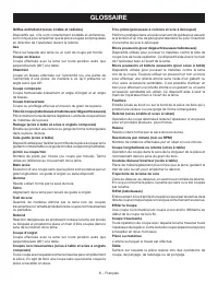
8 − Français GLOSSAIRE Trou pilote (perceuses à colonne et scie à découper) Petit trou pratiqué dans une pièce servant de guide pour assurer la précision d’un trou de plus grand diamètre ou pour l’insertion d’une lame de scie à découper. Blocs poussoirs (pour dégauchisseuses/raboteuses) Dispositifs ...
Page 51 - CARACTÉRISTIQUES; FICHE TECHNIQUE
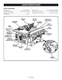
9 − Français CARACTÉRISTIQUES FICHE TECHNIQUE Axe de lame ................................................16 mm (5/8 po)Diamètre de la lame........................... 209,5 mm (8-1/4 po)Inclinaison de la lame .............................................. 0˚ - 45˚Alimentation...........................
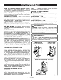
Page 53 - COMPOSANTS FONCTIONNELS; ENSEMBLE DE COMMUTATEUR; COMMUTATEUR EN
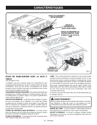
11 − Français CARACTÉRISTIQUES VOLANT DE RÉGLAGE DE HAUTEUR / BISEAU - Situé sur le devant de la scie, ce volant permet d’abaisser et relever la lame pour effectuer les réglages ou les remplacements. Il permet également de régler facilement l’angle de biseau. GUIDE D’ONGLET - Le guide d’onglet align...
Page 54 - OUTILS NÉCESSAIRES
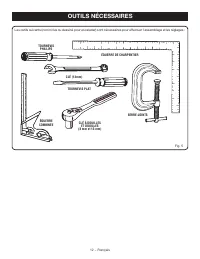
12 − Français OUTILS NÉCESSAIRES Les outils suivants (non inclus ou dessiné pour escalader) sont nécessaires pour effectuer l’assemblage et les réglages : ÉQUERRE DE CHARPENTIER TOURNEVIS PHILLIPS TOURNEVIS PLAT CLÉ À DOUILLES ET DOUILLES (8 mm et 13 mm) ÉQUERRE COMBINÉE SERRE-JOINTS CLÉ (13mm) Fig....
Page 55 - PIÈCES DÉTACHÉES
PIÈCES DÉTACHÉES 13 − Français Les articles suivant sont inclus avec la scie à table : A. Garde de lame avec griffes antiretour...................... 1 B. Ensemble de poignée .............................................. 1 C. Capuchon du bout de la poignée ............................ 1 D. Clé hex....
Page 56 - DÉBALLAGE; ASSEMBLAGE
14 − Français DÉBALLAGE Ce produit doit être assemblé. Sortir la scie du carton avec précaution et la poser une un plan de travail stable. NOTE : Cet outil est lourd. Pour éviter des problèmes lombaires, garder les genous pliés, soulever avec les jambes, pas avec le dos et demander de l’aide lorsq...
Page 57 - TROUS DE MONTAGE
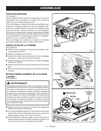
15 − Français ASSEMBLAGE TROUS DE MONTAGE Voir la figure 7. La scie à table doit être montée solidement sur un plan de travail ferme, tel qu’un établi ou un stand. Pour ce faire, la cadre de la scie comporte quatre trous. Pour le montage sur un établi, les boulons doivent être assez longs pour trave...
Page 58 - Nettoyer les plaques du levier; EN « HAUT » POSITION POUR TOUT PAR TRAVERSANTE
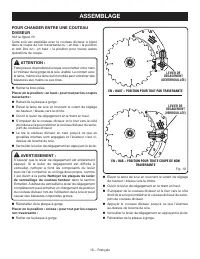
16 − Français ASSEMBLAGE POUR CHANGER ENTRE UNE COUTEAU DIVISEUR Voir la figure 10. Cette scie est expédiée avec le couteau diviseur a placé dans la coupe de non traversante ou « en bas » la position et doit être en.« en haut » la position pour toutes autres opérations de coupe. ATTENTION : Faire pr...
Page 60 - INSTALLATION DE PROTÈGE-LAME; parallèle à la table
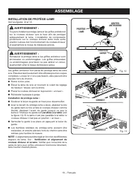
18 − Français ASSEMBLAGE INSTALLATION DE PROTÈGE-LAME Voir les figures 12 et 13. AVERTISSEMENT : Toujours installer le protège-lame et les griffes antirebond sur le couteau diviseur vers le haut afin de protéger adéquatement la lame. L’installation de composants protecteurs sur le couteau diviseur d...
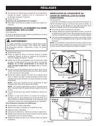
Page 61 - Vérification de l’alignement du couteau diviseur :
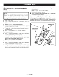
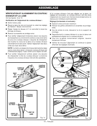
19 − Français ASSEMBLAGE VÉRIFICATION ET ALIGNEMENT DU COUTEAU DIVISEUR ET LA LAME Voir les figures 14 et 15. Vérification de l’alignement du couteau diviseur : Retirer le bloc-piles. Élever la lame de scie en tournant le volant de réglage de hauteur / biseau vers la droite. Régler l’angle du ...
Page 63 - UTILISATION; LOGEMENT DE
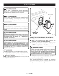
21 − Français INSTALLATION/RETRAIT DU BLOC-PILES Voir la figure 20. Insérer le bloc-piles dans la scie. Aligner la saillie du bloc de piles sur la rainure de l’intérieur de la scie. S’assurer que les loquets sur les deux côtés de la pile s’engagent correctement et vérifier que le bloc-piles es...
Page 64 - CAUSES DE REBONDS
22 − Français UTILISATION CAUSES DE REBONDS Un rebond peut se produire lorsque la lame se bloque ou se coince et propulse violemment la pièce à couper en direction de l’opérateur. Si les mains se trouvent près de lame, elles pourraient être éjectées de la pièce et entrer en contact avec la lame. Il ...
Page 65 - CONSEILS DE COUPE
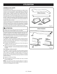
23 − Français UTILISATION CONSEILS DE COUPE Voir les figures 21 et 22. Les bâtons poussoir permettent de pousser une pièce contre la lame en toute sécurité dans coupe longitudinal. En faiant les coupes de non traversante ou refente des planches étroites toujours utiliser un bâton poussoir, bloc pous...
Page 67 - COMMENT INSTALLER UNE CALE-GUIDE; COMMENT FABRIQUER UNE CALE-GUIDE
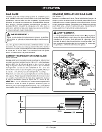
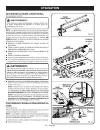
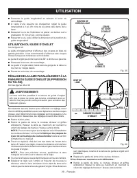
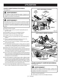
25 − Français LEVIER DE VERROUILLAGE DE LA COUPE EN BISEAU COMMENT INSTALLER UNE CALE-GUIDE Voir la figure 27. Abaisser complètement la lame. Placer le guide longitudinal à la distance voulue de la lame pour la coupe et le verrouiller. Placer la pièce à couper contre le guide à proximité de la lame....
Page 68 - COUPE LONGITUDINALE EN BISEAU; TYPES DE COUPE
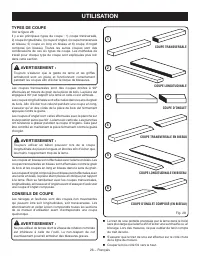
26 − Français UTILISATION COUPE LONGITUDINALE EN BISEAU COUPE LONGITUDINALE COUPE TRANSVERSALE COUPE D’ONGLET COUPE D’ONGLET COMPOSÉ (EN BISEAU) COUPE TRANSVERSALE EN BISEAU 1 TYPES DE COUPE Voir la figure 28. Il y a six principaux types de coupe : 1) coupe transversale, 2) coupe longitudinale, 3) c...
Page 69 - RÉGLAGE DE LA PROFONDEUR DE LAME
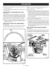
27 − Français UTILISATION Retirer les noeuds décollés à l’aide d’un marteau avant d’effectuer la coupe. Toujours utiliser un support adéquat sous une planche à la sortie de la scie. RÉGLAGE DE LA PROFONDEUR DE LAME Voir la figure 29. La profondeur de coupe doit être réglée pour que les pointes e...
Page 70 - UTILISATION DU GUIDE LONGITUDINAL
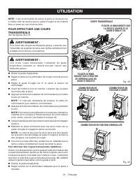
28 − Français UTILISATION UTILISATION DU GUIDE LONGITUDINAL Voir les figures 32 et 33. AVERTISSEMENT : Pour réduire le risque de blessures, toujours vérifier que le guide longitudinal est parallèle à la lame avant de commencer une coupe. NOTE : Le guide longitudinal fourni avec la scie possède un gu...
Page 71 - UTILISATION DU GUIDE D’ONGLET
29 − Français Desserrer le guide longitudinal en relevant le levier de verrouillage. À l’aide d’une équerre de charpentier, régler le guide longitudinal à 2 po (51 mm) de la pointe des dents de la lame. Desserrer la vis de l’indicateur et placer ce dernier sur la graduation 51 mm (2 po), comme...
Page 72 - EXÉCUTION DE COUPES
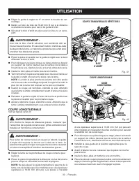
30 − Français Desserrer les boulons de verrouillage en tournant vers la gauche. NOTE : Les boulons sont situés au-dessus du volant à main d’ajustement de la hauteur/du biseau et au-dessous de la scie à table sur le devant de la scie. Tourner le boulon d’ajustement vers la gauche ou la droite jus...
Page 74 - COUPE LONGITUDINALE
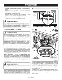
32 − Français UTILISATION Régler le guide à onglet sur 0° et serrer le bouton de ver- rouillage. Mettre un bloc de bois de 76,20 mm (3 po) à la distance souhaitée de la lame pour servir de guide d’arrêt. Sécuriser le bloc d’arrêt en place avec un étau ou un serre- joint. AVERTISSEMENT : Une fo...
Page 78 - COUPE D’UNE PIÈCE DE GRANDE TAILLE
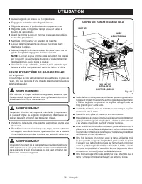
36 − Français Ajuster le guide de biseau sur l’angle désiré. Engager le levier de verrouillage de biseau. Régler la lame sur la profondeur de coupe correcte. Régler le guide d’onglet sur l’angle voulu et serrer le bouton de verrouillage. Avant de mettre la scie en marche, s’assurer que le ...
Page 79 - COUPE NON TRAVERSANTE
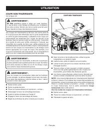
37 − Français COUPE NON TRAVERSANTE Voir la figure 50. AVERTISSEMENT : NE PAS installation lames à rainer sur cette machine. L’ axe de lame a des filetage insuffisants pour installation une lame à rainer. Monter une lame à rainer pourrait avoir pour résultat le risque des blessures graves. Les coupe...
Page 80 - REMPLACEMENT DE LA LAME; RÉGLAGES
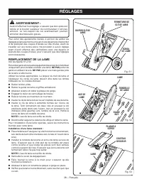
38 − Français AVERTISSEMENT : Avant d’effectuer tout réglage, s’assurer que bloc-piles est retirée et le bouton supérieur du commutateur n’est pas enfoncé. Le non-respect de cet avertissement pourrait entraîner des blessures graves. Pour éviter des ajustements inutiles, il est bon de vérifier les ré...
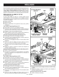
Page 81 - RÉGLAGE DE LA LAME À 0° ET 45°
39 − Français RÉGLAGES Après l’installation, ajuster l’indicateur de l’échelle de refente pour tenir compte du trait et de l’épaisseur de la lame. Rapportez-vous à Pour régler l’échelle graduée sur la lame dans la section Utilisation dans ce manuel. Lors de la coupe, l’échelle doit être placée du cô...
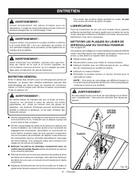
Page 83 - ENTRETIEN GÉNÉRAL; ENTRETIEN; LUBRIFICATION; LEVIER DE
41 − Français AVERTISSEMENT : Utiliser exclusivement des pièces d’origine pour les réparations. L’usage de toute autre pièce pourrait créer une situation dangereuse ou endommager l’outil. AVERTISSEMENT : Toujours porter une protection oculaire certifiée conforme à la norme ANSI Z87.1 lors de l’utili...
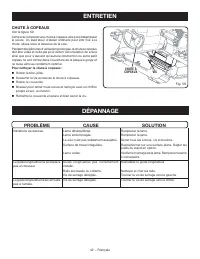
Page 84 - CHUTE À COPEAUX; PROBLÈME; CHUTE À
42 − Français ENTRETIEN CHUTE À COPEAUX Voir la figure 59. Cette scie comprend une chute à copeaux utile pour débarrasser la sciure. Un aspirateur d’atelier ordinaire peut être fixé à la chute, située sous le dessous de la scie.Pendant des périodes d’utilisation prolongée, la chute à copeaux doit êt...
Page 86 - ÁREA DE TRABAJO; Mantenga limpia y bien iluminada el área de trabajo.; SEGURIDAD ELÉCTRICA; REGLAS DE SEGURIDAD GENERALES
2 − Español ADVERTENCIA: L e a t o d a s l a s a d v e r t e n c i a s , i n s t r u c c i o n e s , ilustraciones y especificaciones proporcionadas con esta herramienta eléctrica. No seguir las instrucciones indicadas a continuación puede provocar descargas eléctricas, incendios o lesiones graves. ...
Page 87 - Mantenga las herramientas de corte afiladas y limpias.; SERVICIO
3 − Español EMPLEO Y CUIDADO DE LA HERRAMIENTA ELÉCTRICA No fuerce la herramienta eléctrica. Utilice la herramienta eléctrica adecuada para cada trabajo. La herramienta eléctrica adecuada efectúa mejor y de manera más segura el trabajo, si además se maneja a la velocidad para la que está diseñada....
Page 88 - REGLAS DE SEGURIDAD SIERRA DE MESA; ADVERTENCIAS PROCEDIMIENTOS DE CORTE
4 − Español REGLAS DE SEGURIDAD SIERRA DE MESA ADVERTENCIAS RELACIONADAS CON LA PROTECCIÓN Mantenga los protectores en su lugar. Los protectores deben funcionar correctamente y colocarse de forma apropiada. Repare o reemplace el protector si está flojo, dañado o no funciona correctamente. Use si...
Page 90 - ADVERTENCIAS DE SEGURIDAD ADICIONALES; Haga su taller a prueba de niños, con candados,
6 − Español ADVERTENCIAS DE SEGURIDAD ADICIONALES Familiarícese con su herramienta eléctrica. Lea cuidadosamente el manual del operador. Aprenda los usos y limitaciones de la sierra, así como los posibles peligros específicos de esta herramienta. Haga su taller a prueba de niños, con candados, i...
Page 91 - SÍMBOLOS; SÍMBOLO
7 − Español SÍMBOLOS Es posible que se empleen en esta herramienta algunos de los siguientes símbolos. Le suplicamos estudiarlos y aprender su significado. Una correcta interpretación de estos símbolos le permitirá utilizar mejor y de manera más segura la herramienta. SÍMBOLO NOMBRE DENOMINACIÓN/EXP...
Page 92 - GLOSARIO DE TÉRMINOS
8 − Español GLOSARIO DE TÉRMINOS es un corte en el cual la hoja no corta la pieza de trabajo en dos pedazos. Agujero guía (taladradoras de columna y sierras caladoras) Es un agujero pequeño taladrado en una pieza de trabajo, el cual sirve como guía para taladrar con precisión agujeros más grandes o ...
Page 93 - CARACTERÍSTICAS; ESPECIFICACIONES DEL PRODUCTO
9 − Español CARACTERÍSTICAS ESPECIFICACIONES DEL PRODUCTO Árbol de la hoja de corte ........................ 16 mm (5/8 pulg.)Diámetro de la hoja ....................... 209,5 mm (8-1/4 pulg.)Inclinación de la hoja ............................................... 0˚ - 45˚ Corriente de entrada ..........
Page 94 - FAMILIARÍCESE CON LA SIERRA DE MESA; GAUGE, AND BLADE WRENCH
10 − Español FAMILIARÍCESE CON LA SIERRA DE MESA Vea las figuras 2 y 3. El uso seguro que este producto requiere la comprensión de la información impresa en la herramienta y en el manual del operador así como ciertos conocimientos sobre el proyecto a realizar. Antes de usar este producto, familiaríc...
Page 95 - COMPONENTES DEL FUNCIONAMIENTO; CONJUNTO DEL INTERRUPTOR; INTERRUPTOR EN
11 − Español CARACTERÍSTICAS VOLANTE DE AJUSTE DE ALTURA Y BISEL - Este volante, situado en la parte delantera de la sierra, sirve para subir y bajar la hoja con el fin de efectuar ajustes a la altura de la misma, o reemplazarla. Este volante también facilita el ajuste del ángulo de biselado. GUÍA D...
Page 96 - HERRAMIENTAS NECESARIAS
12 − Español HERRAMIENTAS NECESARIAS ESCUADRA DE CARPINTERO LLAVE 13 mm DESTORNILLADOR DE PUNTA PLANA DESTORNILLADOR DE CABEZA PHILLIPS ESCUADRA DE COMBINACIÓN LLAVE DE CASQUILLO Y CUBOS CUADRADOS (8 mm y 13 mm) PRENSAS EN C Para armar la unidad y efectuar ajustes se necesitan las siguientes herrami...
Page 97 - PIEZAS SUELTAS
PIEZAS SUELTAS 13 − Español Con la sierra de mesa vienen incluidos los siguientes artículos: Fig. 6 A. Protección de la hoja con trinquetes anticontragolpe ....................................... 1 B. Conjunto del mango ................................................ 1 C. Tapa del extremo del mango...
Page 98 - DESEMPAQUETADO; ARMADO
14 − Español DESEMPAQUETADO Este producto requiere armarse. Levante cuidadosamente de la caja la sierra y colóquela sobre una superficie de trabajo nivelada. NOTA: Esta herramienta es pesada. Para evitar lesionarse la espalda, mantenga dobladas las rodillas, levante con las piernas, no con la espa...
Page 99 - AGUJEROS DE MONTAJE
15 − Español ARMADO AGUJEROS DE MONTAJE Vea la figura 7. La sierra de mesa debe montarse en una superficie de soporte firme, como un banco de trabajo o un pedestal de patas. Hay cuatro agujeros para perno en la armazón de la sierra para este fin. Si se atornilla a un banco de trabajo, los pernos deb...
Page 101 - PARA REVISAR LA INSTALACIÓN DE LA HOJA; CIERRE EL LLAVE
17 − Español ARMADO PARA REVISAR LA INSTALACIÓN DE LA HOJA DE LA SIERRA Vea la figura 11. AVISO: Para funcionar correctamente, los dientes de la hoja deben apuntar hacia la parte frontal de la sierra, hacia abajo. La inobservancia de esta advertencia podría causar daños a la hoja de la sierra, la si...
Page 102 - PARA INSTALAR EL PROTECCIÓN DE LA HOJA
18 − Español ARMADO PARA INSTALAR EL PROTECCIÓN DE LA HOJA Vea las figuras 12 y 13. ADVERTENCIA: Instale siempre la protección de la hoja y las garras que no permiten el retroceso en la cuchilla separadora en la posición “ascendente” para suministrar una cobertura de hoja adecuada. Instalar los comp...
Page 104 - ALMACENAMIENTO DE ACCESORIOS DE LA
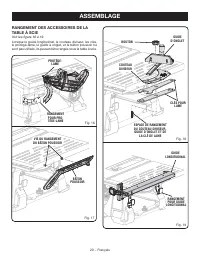
20 − Español ARMADO ALMACENAMIENTO DE ACCESORIOS DE LA SIERRA DE MESA Vea las figuras 16 a 19. Cuando no estén en uso, la guía de corte al hilo, la cuchilla separadora, las llaves, la protección de la hoja, el medidor de inglete, y el palo empujador pueden guardarse debajo de la mesa de la sierra. F...
Page 105 - FUNCIONAMIENTO; APLICACIONES; RECEPTÁCULO
21 − Español PARA INSTALAR/DESMONTAR EL PAQUETE DE BATERÍAS Vea la figura 20. Coloque el paquete de baterías en la sierra. Alinee la costilla realzada del paquete de baterías con la ranura situada dentro de la sierra. Asegúrese de que los pestillos situados en ambos lados del paquete de baterí...
Page 106 - CAUSAS DE LOS CONTRAGOLPES
22 − Español FUNCIONAMIENTO CAUSAS DE LOS CONTRAGOLPES El contragolpe puede ocurrir cuando la hoja se atasca o dobla, lanzando la pieza de trabajo hacia atrás, hacia usted, con gran fuerza y velocidad. Si tiene las manos cerca de la hoja de la sierra, pueden soltarse de la pieza de trabajo y tocar l...
Page 107 - AYUDAS PARA CORTAR
23 − Español FUNCIONAMIENTO AYUDAS PARA CORTAR Vea las figuras 21 y 22. Las estacas empujadoras son dispositivos empleados para empujar la pieza de trabajo por la hoja en cualquier corte al hilo. Al hacer cortes de no pasante o longitudinal estreche acciones, sempre utilice un palos empujadora, bloq...
Page 108 - SOPORTES DE LA PIEZA DE TRABAJO
24 − Español FUNCIONAMIENTO SOPORTES DE LA PIEZA DE TRABAJO Vea la figura 23. Cuando corte con la sierra de mesa, asegúrese de que la pieza de trabajo esté bien sujetada. El soporte adecuado de la pieza de trabajo durante el proceso de corte no solo mejora la precisión del corte, sino que también pe...
Page 109 - FORMA DE MONTAR UN PEINE DE SUJECIÓN; PEINES DE SUJECIÓN
25 − Español completamente antes de retirar la tabla. Reajuste la guía de corte al hilo y haga cortes espaciados en la pieza de trabajo para dejar dedos de 6,4 mm (1/4 pulg.) y 3,2 mm (1/8 pulg.) de espacio entre los dedos aproximadamente. FORMA DE MONTAR UN PEINE DE SUJECIÓN Vea la figura 27. Baje ...
Page 110 - TIPOS DE CORTES
26 − Español FUNCIONAMIENTO ADVERTENCIA: El peine de sujeción debe ser instalado delante de la hoja. No coloque el peine de sujeción en la parte posterior de la hoja. Si se coloca inadecuadamente, puede producirse un contragolpe al apretar el peine de sujeción la pieza de trabajo y doblar la hoja en...
Page 111 - SUGERENCIAS PARA RECORTAR
27 − Español FUNCIONAMIENTO SUGERENCIAS PARA RECORTAR Los cortes de ranurado y rebajado son cortes sin traspaso del espesor de la tabla, y pueden ser cortes al hilo o transversales. Lea cuidadosamente y comprenda todas las secciones de este manual del operador antes de intentar cualquier operación. ...
Page 112 - PARA AJUSTAR EL INDICADOR DE BISEL
28 − Español FUNCIONAMIENTO gírela a la izquierda. Después suelte la palanca de fijación de biseles y permita que regrese a su posición original. Gírela de nuevo a la derecha. Repita este proceso hasta dejar apretada firmemente la palanca de fijación de bisel. PARA AJUSTAR EL INDICADOR DE BISEL Vea ...
Page 113 - PARA USAR LA GUIA DE INGLETES
29 − Español de bloqueo de la guía de corte al hilo , en la sección Ajuste de este manual. NOTA: Si la guía de corte al hilo no está en posición paralela a la hoja, deberá realizar ajustes. Consulte: Verificacion del alineamiento de la guía de corte al hilo en relacion a la hoja en la sección Ajuste...
Page 114 - FORMA DE EFECTUAR CORTES
30 − Español NOTA: Para obtener detalles sobre cómo retirar y volver a colocar la cuchilla separadora, consulte Cómo limpiar las placas de la palanca de bloqueo de la cuchilla separadora en la sección Mantenimiento de este manual. Marque un lado de uno de los dientes de la parte frontal de la hoja...
Page 115 - PARA EFECTUAR CORTES TRANSVERSALES
31 − Español FUNCIONAMIENTO ADVERTENCIA: No utilice hojas con una velocidad nominal inferior a la de esta herramienta. La inobservancia de esta advertencia podría causar lesiones corporales. Utilice la guía de ingletes cuando efectúe cortes trans-versales, a inglete, en bisel y a inglete combinados....
Page 116 - CÓMO EFECTUAR CORTES AL HILO
32 − Español FUNCIONAMIENTO Permita que la hoja alcance la velocidad plena antes de mover la pieza de trabajo hacia la hoja. Sostenga firmemente la pieza de trabajo con ambas manos en la guía de ingletes y alimente la pieza a la hoja de corte. NOTA: La mano más cercana a la hoja debe colocarse e...
Page 118 - CÓMO EFECTUAR CORTES A INGLETE
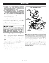
34 − Español NOTA: Esta técnica sirve para hacer cortes al hilo estrechos en piezas de trabajo de 19,05 mm (3/4 pulg.) de espesor o menos. Para hacer cortes al hilo estrechos en materiales más gruesos, use una plantilla de corte al hilo estrecho; consulte Cómo Hacer una vaivén (para el corte al hilo...
Page 119 - CÓMO EFECTUAR CORTES AL HILO EN BISEL
35 − Español Fije la guía de ingletes a 0° y apriete la perilla de la mordaza de ajuste. Asegúrese de que la pieza de trabajo está lejos de la hoja antes de encender la sierra. Inserte el paquete de baterías y encienda la sierra. Permita que la hoja alcance la velocidad plena antes de mover ...
Page 120 - CÓMO CORTAR UN PANEL GRANDE
36 − Español CÓMO EFECTUAR CORTES A INGLETE COMBINADOS (EN BISEL) Vea la figura 48. ADVERTENCIA: Asegúrese de que esté instalado y funcione adecuadamente Asegúrese de que esté instalado y funcione adecuadamente e l c o n j u n t o p ro t e c c i ó n d e l a h o j a c o n t r i n q u e t e s anticont...
Page 121 - CÓMO EFECTUAR UN CORTE SIN TRASPASO; CORTE SIN TRASPASO
37 − Español la superficie de la mesa. Si corta al hilo una pieza angosta, utilice una palos empujadora y/o bloque empujador para mover la pieza durante el corte a través de la hoja. Cuando termine el corte, apague la sierra. Espere a que la hoja se detenga por completo antes de retirar la pieza d...
Page 122 - PARA REEMPLAZAR LA HOJA; AJUSTES
38 − Español ADVERTENCIA: Antes de efectuar cualquier ajuste, asegúrese de que el paquete de baterías esté retirada y que el botón superior del interruptor no esté presionado. La falta de atención a esta advertencia podría causar lesiones corporales graves. Para evitar configuraciones y ajustes inne...
Page 123 - PARA AJUSTAR LA HOJA DE CORTE A 0°
39 − Español AJUSTES Después de la instalación, ajuste el indicador de escala de corte al hilo para adaptarlo al ancho de corte y el grosor de la hoja. Consulte el apartado Para ajustar a la hoja el indicador de la escala de la guía de corte al hilo en la sección Funcionamiento de este manual. En la...
Page 125 - MANTENIMIENTO GENERAL; MANTENIMIENTO; LUBRICACIÓN; PALANCA PARA
41 − Español ADVERTENCIA: Al dar servicio a la unidad, sólo utilice piezas de repuesto idénticas. El empleo de piezas diferentes puede causar un peligro o dañar el producto. ADVERTENCIA: Siempre póngase protección ocular con la marca de cumplimiento de la norma ANSI Z87.1. Si la operación genera muc...
Page 126 - VERTEDERO DE ASERRÍN; CORRECCIÓN DE PROBLEMAS; PROBLEMA; VERTEDERO
42 − Español MANTENIMIENTO VERTEDERO DE ASERRÍN Vea la figura 59. Esta sierra incluye un vertedero de aserrín práctico para descargar el aserrín. Puede conectar una aspiradora común al vertedero de aserrín, ubicado debajo de la parte trasera de la sierra.Durante períodos de uso prolongado, el verted...


 Ryobi PBLTS01B
User Manual
Ryobi PBLTS01B
User Manual
 Ryobi PBLTS01K
User Manual
Ryobi PBLTS01K
User Manual
 Ryobi PBLTS01K-PBT01B
User Manual
Ryobi PBLTS01K-PBT01B
User Manual
 Ryobi PGC21B-A06F551
User Manual
Ryobi PGC21B-A06F551
User Manual
 Ryobi PGC21K
User Manual
Ryobi PGC21K
User Manual
 Ryobi PGC21K-A06F551
User Manual
Ryobi PGC21K-A06F551
User Manual
 Ryobi RTS08
User Manual
Ryobi RTS08
User Manual
 Ryobi RTS12
User Manual
Ryobi RTS12
User Manual
 Ryobi RTS23
User Manual
Ryobi RTS23
User Manual
 Ryobi RTS23-PBLDD01K
User Manual
Ryobi RTS23-PBLDD01K
User Manual
 Ryobi RTS23-RHTM25
User Manual
Ryobi RTS23-RHTM25
User Manual