Page 2 - SPECIFICATIONS
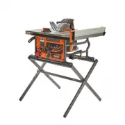
TABLE OF CONTENTS FUNCTIONAL DESCRIPTION SPECIFICATIONS The RIDGID ® #R4540 series 10 inch Portable Contractor Table Saw is designed for portability and high quality performance. It includes: basic machine, sturdy tubular steel stand, integral 2 1/2 inch dust chute, a fence system, T-slot miter gaug...
Page 3 - FEATURES
FEATURES F9 F10 F11 F12 F13 F14 F15 Bevel Lock Lever Height Adjustment Wheel KnobStand On/Off Switch Saw Body Push Stick Rails Rip Fence F9 F10 F11 F12 F13 F14 F15 F16 F16 F17 F18 F19 F20 Flip Down Fence Saw Blade Anti-Kickback Pawls Riving Knife Dust Chute F17 F18 F19 F20 F21 F21 F5 F6 F7 F8 F1 F2 ...
Page 4 - IMPORTANT SAFETY INSTRUCTIONS
Some of the following symbols may be used on the tool. Please study them and learn their meaning. Proper interpretation on these symbols will allow you to operate the tool better and safer. SYMBOL NAME DESIGNATION/EXPLANATION Safety Alert Indicates a potential personal injury hazard. Read Operator's...
Page 5 - GENERAL POWER TOOL SAFETY WARNINGS
The term “power tool” in the warnings refers to your mains-operated (corded) power tool or BATTERY-operated (cordless) power tool. 1. Work area safety a. Keep work area clean and well-lit. Cluttered or dark areas invite accidents. b. Do not operate power tools in explosive atmospheres, such as in th...
Page 6 - TABLE SAW SAFETY RULES; TABLE SAW SPECIFIC SAFETY RULES; TERMINOLOGY
TABLE SAW SAFETY RULES Failure to follow these rules may result in serious personal injury. SEE GENERAL POWER TOOL SAFETY SECTION OF THIS MANUAL. Read entire instruction manual before operating saw. Learning the saw’s proper applications, limitations, and specific potential hazards will greatly mini...
Page 8 - PROPOSITION 65 WARNING:; SAVE THESE INSTRUCTIONS.; SAW BLADE GUARD, ANTI-KICKBACK PAWLS AND RIVING KNIFE; KICKBACKS
PROPOSITION 65 WARNING: SAVE THESE INSTRUCTIONS. Refer to them often and use them to instruct others. • If tool is loaned to someone, also loan them these instructions. Dust created by power sanding, sawing, grinding, drilling, and other construction activities may contain chemicals known to the sta...
Page 9 - POWER CONNECTIONS; POWER SOURCE; EXTENSION CORDS; UNPACKING
POWER CONNECTIONS POWER SOURCE This saw is equipped with a 15-amp motor for use with a 120- volt, 60-HZ alternating current. For voltage, the wiring in a shop is as important as the motor’s rating. A line intended only for lights may not be able to properly carry the current needed for a power tool ...
Page 10 - PACKAGE CONTENTS
UNPACKING PACKAGE CONTENTS Saw Body Fence 10 inch Carbide Tipped Blade Miter Gauge Blade Guard Assembly Anti-Kickback Pawls Throat Plate Open End Blade Wrench Closed End Blade Wrench Push Stick Stand Part 1 Stand Part 2 Stand Legs PC1 PC1 PC2 PC2 PC3 PC3 PC4 PC4 PC5 PC5 PC6 PC6 PC7 PC7 PC8 PC8 PC9 P...
Page 11 - HARDWARE BAG CONTENTS
M8 x 30mm (1 3/16 inch) Carriage Bolt (8) Flat Washer 8mm x 14mm x 1.5T (4) M8 Plastic Spacer (2) M8 x 65mm Hex Socket Head Screw (2) M8 Lock Nut (10) M8 x 55L Pan Head Hex Socket Screw (4) HARDWARE BAG CONTENTS UNPACKING HP6 HP6 HP5 HP5 HP4 HP4 HP3 HP3 HP2 HP2 HP1 HP1 006511 005733 006510 005733 00...
Page 13 - ASSEMBLY; ASSEMBLING THE STAND
1. Assemble Stand Part 2 PC12 through Stand Part 1 PC11 that has the cross support as shown in Figure 1. ASSEMBLY When lifting saw, hold it close to your body. Keep knees bent and lift with your legs, not your back. Fully assemble Saw with Stand Assembly prior to use. Stand Assembly is an integral a...
Page 14 - ATTACHING STAND TO SAW
ASSEMBLY ATTACHING STAND TO SAW 1. Place Saw Body PC1 on Stand Assembly, while aligning the screw holes in the Saw Stand with the threaded holes in the Saw Base. See Figure 5. 2. Tighten Hex Cap Screws, with supplied Combination 4mm Allen Wrench HP8 to secure Stand Assembly to Saw. NOTE: DO NOT over...
Page 15 - HEIGHT ADJUSTMENT KNOB; UNLOCK; INSTALLING THE BLADE
ASSEMBLY HEIGHT ADJUSTMENT KNOB INSTALLATION 1. Insert Wheel Handle Shoulder Screw HP7 into Height Adjustment Wheel Knob HP8 as shown in Figure 6. 2. Tighten Shoulder Screw with Phillips Screw Driver into the Hand Wheel. Height adjustment Wheel Knob should rotate freely around Shoulder Screw when ra...
Page 16 - THROAT PLATE
ASSEMBLY To reduce the risk of serious injury: 1. The Riving Knife must be installed for every through cut and for every non-through cut unless the Riving Knife A would interfere with the cut. 2. The Riving Knife provided with the Table Saw shall be thicker than the body of the matching Saw Blade pr...
Page 17 - ANTI-KICKBACK PAWLS AND BLADE GUARD; BLADE GUARD
ASSEMBLY FIGURE 13 ANTI-KICKBACK PAWLS AND BLADE GUARD ANTI-KICKBACK PAWLS To reduce the risk of serious personal injury, Anti-Kickback Pawls PC6 must be in place when making a through cut. 1. Refer to Figure 13 and locate the Anti-Kickback Pawls Mounting Slot in the middle of the top edge of the Ri...
Page 18 - INSTALLING THE FENCE
ASSEMBLY FIGURE 17 INSTALLING THE FENCE The fence can be positioned on one of the three pairs of tabs. Two on the right side of the blade and one on the left side. 1. Hold fence perpendicular to the table. 2. Starting with the rear of the fence, engage the rear notch on the rear tab. 3. Lower the fr...
Page 19 - LEVELING THE THROAT PLATE
ASSEMBLY FIGURE 19 FIGURE 20 ON-BOARD STORAGE Storage is located on the left side and right side of the Tool as shown in Figures 19 & 20. Right Side Storage Figure 20: Blade Wrenches R i v i n g K n i f e ( w i t h B l a d e Wrenches)Blade Guard Assembly Anti-Kickback Pawls (Behind Blade Guard A...
Page 20 - MAKING ADJUSTMENTS; ADJUSTING BLADE PARALLEL TO
MAKING ADJUSTMENTS FIGURE 22 FIGURE 23 ADJUSTING BLADE PARALLEL TO MITER GAUGE GROOVE (HEEL) • Blade A must be parallel to miter gauge groove so that wood does not bind, resulting in kickback. Failure to do so could result in serious personal injury. • To reduce risk of injury from kickback, align r...
Page 22 - ADJUSTING THE BEVEL STOPS; Adjusting 0 Degree Positive Stop; Adjusting 45 Degree Positive Stop; CAM; SQUARING THE BLADE
MAKING ADJUSTMENTS UNLOCK UNLOCK UNLOCK UNLOCK LOCK LOCK LOCK LOCK FIGURE 28 FIGURE 29 ADJUSTING THE BEVEL STOPS Adjusting 0 Degree Positive Stop If the blade is not vertically square to the table, you MUST adjust the 0° positive stop, located on the far left end of the bevel track as shown in Figur...
Page 23 - ADJUSTING THE BLADE HEIGHT
MAKING ADJUSTMENTS FIGURE 30 ADJUSTING THE BLADE HEIGHT 1. For all through cuts, the top of the blade points should be above the workpiece and the bottom of the blade gullets are below the top surface of workpiece. 2. For non-through cuts, the top of the blade points should be set to the depth of th...
Page 24 - USING COLOR-CODED SCALES; BLACK PEG
MAKING ADJUSTMENTS FIGURE 33 FIGURE 35 FIGURE 34 USING COLOR-CODED SCALES The black pegs correspond to the black scale with white numbers.• The black tabs in the middle of the rail can be used for right rip cut 0 inches to 15 inches. • To use the black scale with white numbers, insert the fence notc...
Page 25 - RIVING KNIFE HEIGHT SETTINGS; RIVING KNIFE POSITION AND ALIGNMENT
RIVING KNIFE HEIGHT SETTINGS The height of the riving knife should be adjusted based on the type of cut being made. For all through cuts (when the wood is completely severed), it should be in the raised position, with anti-kick pawls and guard installed. For non-through cuts (when the blade does not...
Page 26 - RIVING KNIFE ALIGNMENT; Parallel Alignment; Horizontal Alignment; Vertical Alignment
RIVING KNIFE POSITION AND ALIGNMENT FIGURE 38 RIVING KNIFE ALIGNMENT Parallel Alignment The plane of the riving knife B is parallel to the plane of the blade A but the riving knife and the blade are not in line with each other. If a parallel adjustment is required use Figure 37 and Figure 38 to make...
Page 27 - MOVING THE SAW; OPERATION
RIVING KNIFE POSITION AND ALIGNMENT FIGURE 41 MOVING THE SAW Once the saw is removed from the stand, it is recommended that the saw be moved using two people. A possible carry point is the handle located on the right side of the saw. As seen in Figure 41. OPERATION Failure to comply with the followi...
Page 28 - TURNING THE SAW ON AND OFF; DUST COLLECTOR; LOCK
OPERATION TURNING THE SAW ON AND OFF The ON/OFF paddle switch is located on the left side of the front panel of the saw. 1. Press the green “ON” button. 2. Press the switch down to turn the saw OFF. 3. When not in use, the saw should be turned off and the power switch locked out to prevent unauthori...
Page 29 - MAKING CUTS
MAKING CUTS Failure to comply with the following warnings may result in serious personal injury. • NEVER touch the free end of the workpiece or a free piece that is cut off, while the power is on and/or the saw blade is rotating. Blade contact or binding may occur, resulting in a thrown workpiece. •...
Page 30 - RIP CUTS; BEVEL RIPPING
MAKING CUTS Bevel ripping is the same as ripping except the bevel angle A is set to an angle other than 0°. When making a bevel rip cut, place the fence on the right side of the blade so that the blade is tilted away from the fence and hands. See Figure 45. FIGURE 45 RIP CUTS 1. Remove miter gauge. ...
Page 31 - CROSSCUTTING; BEVEL CROSSCUTTING
FIGURE 47 MAKING CUTS CROSSCUTTING miter gauge and attach workpiece to auxiliary face. For instructions about making auxiliary faces, see CUTTING AIDS section on page 33 of this manual. 7. Make sure the workpiece is clear of the blade - at least 1 inch or 25mm away - before starting the saw. 8. Turn...
Page 32 - COMPOUND MITER CUTS; MAKING A NON-THROUGH CUT
MAKING CUTS COMPOUND MITER CUTS This is a combination of bevel crosscutting and mitering. Refer to Figure 48 and follow the instructions for both bevel crosscutting and mitering. Remember to use the right miter slot on the right side of the blade for all bevel cuts. LARGE PANEL CUTS Place workpiece ...
Page 33 - CUTTING AIDS AND ACCESSORIES; PUSH STICK; IN OFFICE
CUTTING AIDS AND ACCESSORIES PUSH STICK In order to operate your table saw safely, you must use a push stick whenever the size or shape of the workpiece would otherwise cause your hands to be within 6 inches (152mm) of the saw blade or other cutter. A push stick is included with this saw. No special...
Page 34 - AUXILIARY MITER GAUGE FACING; PUSH BLOCK
CUTTING AIDS AND ACCESSORIES AUXILIARY MITER GAUGE FACING AUXILIARY FENCE (FLIP DOWN) An auxiliary miter gauge facing is used to increase the surface area of the miter gauge face. The use of miter gauge with auxiliary facing is the same as original miter gauge (without auxiliary facing). See Page 23...
Page 35 - FEATHERBOARD; CUT OFF GAUGE; JIGS
FIGURE 53 FIGURE 54 FIGURE 55 CUTTING AIDS AND ACCESSORIES FEATHERBOARD Featherboards are used to keep the workpiece in contact with the fence and table (see Figure 54), and help prevent kickback. Featherboards are especially useful when ripping narrow workpieces and for completing non-through cuts....
Page 36 - MAINTENANCE; KEEP MACHINE CLEAN
MAINTENANCE To reduce the risk of injury, turn unit off and disconnect it from power source before cleaning or servicing, before installing and removing accessories, before adjusting and when making repairs. An accidental start-up can cause injury. KEEP MACHINE CLEAN Periodically blow out all air pa...
Page 37 - FAILURE TO START
ACCESSORIES TROUBLESHOOTING For assistance with your machine, visit our website at www.RIDGID.com for a list of service centers or call RIDGID ® Customer Service at (toll free) 1-888-359-4778 or email at [email protected]. FAILURE TO START If your machine fails to start, check to make sure the prong...
Page 38 - PARTS, SERVICE OR WARRANTY ASSISTANCE; RIDGID; DPEC
PARTS, SERVICE OR WARRANTY ASSISTANCE Proof of purchase must be presented when requesting warranty service. Limited to RIDGID ® stationary power tools purchased 2/1/21 and after. This product is manufactured by DPEC. The trademark is licensed from RIDGID ® , Inc. All warranty communications should b...
Page 39 - OPERATOR’S MANUAL; 0 INCH PORTABLE CONTRACTOR TABLE SAW; Customer Service Information:
OPERATOR’S MANUAL 10 INCH PORTABLE CONTRACTOR TABLE SAW R4540 DPEC 2651 New Cut Road Spartanburg, SC 29203 ©2021 RIDGID ® is a registered trademark and used under license. DPEC006184 04-28-21 REV6 Customer Service Information: For parts or service, do not return this product to the store. Contact yo...