Omega OF914FX - Manuals
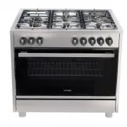
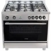
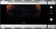
User Manual Omega OF914FX


Summary
WARNINGS: 1. This appliance is not intended for use by persons (including children) with reduced physical, sensory or mental capabilities, or lack of experience or kno wledge, unless they have been given supervision or instruction concerning the use of the appliance by a person re sponsible for ...
LOCAL AUTHORITY REQUIREMENTS Before installation, unpack all parts from carton, remov e all internal packaging and check for damage. Check Gas Type and specifications plate placed on the rear of the unit, alternatively there is a second label supplied – this should be fixed in an accessible posi...
IMPORTANT INFORMATION FOR INSTALLIN G THE APPLIANCE The cooker can be installed separately, a s a fre estanding unit, or betw een kitchen u nits or between a kitchen unit and the wall. This appliance is not connected to devices which e xh a u s t combustion products. Special attention must b...
Omega Ovens Manuals
-
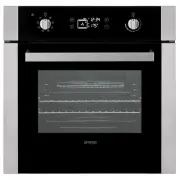
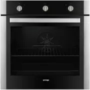 Omega OBO674X
User Manual
Omega OBO674X
User Manual
-
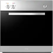
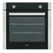 Omega OBO676X
User Manual
Omega OBO676X
User Manual
-
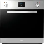
 Omega OF901XZ
User Manual
Omega OF901XZ
User Manual
-
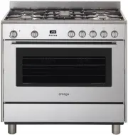
 Omega OF916FX
User Manual
Omega OF916FX
User Manual
-
 Omega OO62PX
User Manual
Omega OO62PX
User Manual
-
 Omega OO651XR
User Manual
Omega OO651XR
User Manual
-
 Omega OO652XR
User Manual
Omega OO652XR
User Manual
-
 Omega OO653X
User Manual
Omega OO653X
User Manual
-
 Omega OO654X
User Manual
Omega OO654X
User Manual
-
 Omega OO656X
User Manual
Omega OO656X
User Manual
-
 Omega OO65SXR
User Manual
Omega OO65SXR
User Manual
-
 Omega OO686X
User Manual
Omega OO686X
User Manual
-
 Omega OO687X
User Manual
Omega OO687X
User Manual
-
 Omega OO6AX
User Manual
Omega OO6AX
User Manual
-
 Omega OO757X
User Manual
Omega OO757X
User Manual
-
 Omega OO885XR
User Manual
Omega OO885XR
User Manual
-
 Omega OO986X
User Manual
Omega OO986X
User Manual
-
 Omega OS450X
User Manual
Omega OS450X
User Manual