Omega OCG755FX - Manuals
User Manual Omega OCG755FX


Summary
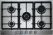
3 NATURAL - U-LPG 1 Double crown Wok burner 15.5 MJ/h 12.6 MJ/h 2 Rapid gas burner 12.0 MJ/h 10.4 MJ/h 3 Semirapid gas burner 7.1 MJ/h 6.3 MJ/h 4 Semirapid reduced gas burner 5.4 MJ/h 4.9 MJ/h 5 Auxiliary gas burner 4.1 MJ/h 3.6 MJ/h 6 Cast iron pan support ( depending on the version) 7 Burner n° 1 ...
4 1) BURNERS A diagram is screen-printed above each knob on the front panel. This diagram indicates to which burner the knob in question corresponds. After having opened the gas mains or gas bottle tap, light the burners as described below: - manual ignition Push and turn the knob corresponding to t...
6 CLEANING Note: continuous use could cause the burners to change colour due to the high temperature. FIG. 6/A IMPORTANT: always disconnect the appliance from the gas and electricity mains before carrying out any cleaning operation. 2) HOT PLATE P e r i o d i c a l l y w a s h t h e h o t p l a t e ...
Omega Hobs Manuals
-
 Omega OC65TA
User Manual
Omega OC65TA
User Manual
-
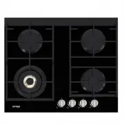
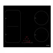
 Omega OCG604XCOM
User Manual
Omega OCG604XCOM
User Manual
-
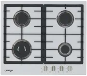
 Omega OCG60X
User Manual
Omega OCG60X
User Manual
-
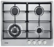
 Omega OCG61X
User Manual
Omega OCG61X
User Manual
-
 Omega OCG61XA
User Manual
Omega OCG61XA
User Manual
-
 Omega OCG62X
User Manual
Omega OCG62X
User Manual
-
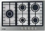
 Omega OCG63FFX
User Manual
Omega OCG63FFX
User Manual
-
 Omega OCG63FX
User Manual
Omega OCG63FX
User Manual
-
 Omega OCG64FFX
User Manual
Omega OCG64FFX
User Manual
-
 Omega OCG64X
User Manual
Omega OCG64X
User Manual
-
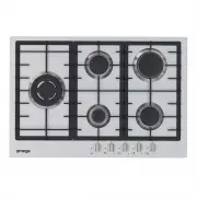
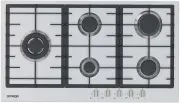
 Omega OCG75FX
User Manual
Omega OCG75FX
User Manual
-
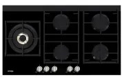
 Omega OCG75FXB
User Manual
Omega OCG75FXB
User Manual
-
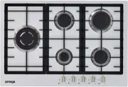 Omega OCG75XB
User Manual
Omega OCG75XB
User Manual
-
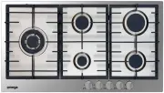
 Omega OCG90FXB
User Manual
Omega OCG90FXB
User Manual
-
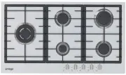
 Omega OCG90X
User Manual
Omega OCG90X
User Manual
-
 Omega OCG90XB
User Manual
Omega OCG90XB
User Manual
-
 Omega OCG95FFX
User Manual
Omega OCG95FFX
User Manual
-
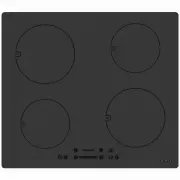
 Omega OCI60MZ
User Manual
Omega OCI60MZ
User Manual
-
 Omega OCI64B
User Manual
Omega OCI64B
User Manual
-
 Omega OCI64PP
User Manual
Omega OCI64PP
User Manual