Page 3 - Safety Instructons; DO NOT LEAVE THIS EQUIPMENT IN AN ENVIRONMENT UNCONDITIONED,
MS-7522 Safety Instructons Always read the safety nstructons carefully.Keep ths User’s Manual for future reference.Keep ths equpment away from humdty.Lay ths equpment on a relable flat surface before settng t up.The openngs on the enclosure are for ar convecton hence protects the equpment from overh...
Page 4 - FCC-B Rado Frequency Interference Statement
v Preface ▍ FCC-B Rado Frequency Interference Statement Ths equpment has been tested and found to comply wth the lmts for a Class B dg- tal devce, pursuant to Part 15 of the FCC Rules. These lmts are desgned to provde reasonable protecton aganst harmful nter- ference n a resdental nstallaton. Ths eq...
Page 5 - WEEE (Waste Electrcal and Electronc Equpment) Statement; ENGLISH; schlesslch an ener lokalen Altgerätesammelstelle n Ihrer Nähe.; FRANÇAIS; эти изделия в специализированные пункты приема.
v MS-7522 WEEE (Waste Electrcal and Electronc Equpment) Statement ENGLISH To protect the global envronment and as an envronmentalst, MSI must remnd you that...Under the European Unon (“EU”) Drectve on Waste Electrcal and Elec- tronc Equpment, Drectve 2002/96/EC, whch takes effect on August 13, 2005,...
Page 6 - Preface; ESPAÑOL; empresa autorzada para la recogda de estos resduos.; NEDERLANDS; lokale nzamelngspunten.; SRPSKI; vode možete vratt na lokalnm mestma za prkupljanje.; POLSKI
v Preface ▍ ESPAÑOL MSI como empresa comprometda con la proteccón del medo ambente, recomenda:Bajo la drectva 2002/96/EC de la Unón Europea en matera de desechos y/o equ- pos electróncos, con fecha de rgor desde el 13 de agosto de 2005, los productos clasficados como “eléctrcos y equpos electróncos”...
Page 7 - TÜRKÇE; noktalarına bırakablrsnz.; ČESKY; cclo d vta. È possble portare prodott nel pù vcno punto d raccolta
v MS-7522 TÜRKÇE Çevrec özellğyle blnen MSI dünyada çevrey korumak çn hatırlatır:Avrupa Brlğ (AB) Kararnames Elektrk ve Elektronk Malzeme Atığı, 2002/96/EC Kararnames altında 13 Ağustos 2005 tarhnden tbaren geçerl olmak üzere, elektrkl ve elektronk malzemeler dğer atıklar gb çöpe atılamayacak ve bu ...
Page 8 - CONTENTS
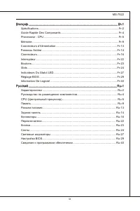
v Preface ▍ CONTENTS Copyrght Notce ............................................................................................ Trademarks .................................................................................................... Revson Hstory.................................................
Page 11 - Englsh; Europe verson
Page 14 - uick
En-4 MS-7522 Manboard ▍ RESET Clr CMOS Q uick c oMponentS G uide Back Panel, En-11 CPU, En-5 DDR3, En-9 JPWR1, En-13 IDE1, En-16 JCI1,En-18 JUSB1~3, En-19 JCOM1, En-20 JPWR2, En-13 CPUFAN1, En-17 J1394_1, En-18 CPU_CLK1, En-22 CLR_CMOS1, En-23 RESET1, En-23 POWER1, En-23 JCD1, En-18 JAUD1, En-19 JFP...
Page 15 - Important
En-5 cpu (c entral p roceSSinG u nit ) When you are nstallng the CPU, make sure to nstall the cooler to prevent overheatng. If you do not have the CPU cooler, consult your dealer before turnng on the computer. For the latest nformaton about CPU, please vst http://www.ms.com/ndex.php?func=cpuform2 Im...
Page 16 - CPU & Cooler Installaton; Algnment Key
En-6 MS-7522 Manboard ▍ CPU & Cooler Installaton When you are nstallng the CPU, make sure the CPU has a cooler attached on the top to prevent overheatng. Meanwhle, do not forget to apply some thermal paste on CPU before nstallng the heat snk/cooler fan for better heat dsperson. Follow the steps ...
Page 19 - Memory Populaton Rules
En-9 M eMory These DIMM slots are used for nstallng memory modules. For more nformaton on compatble components, please vst http://www.ms.com/ndex.php?func=testreport DDR3 240-pn, 1.5V 48x2=96 pn 72x2=144 pn Memory Populaton Rules Please refer to the followng llustratons for memory populaton rules. S...
Page 21 - memory module vender for the thrd channelsupports.
En-11 Important DDR3 memory modules are not nterchangeable wth DDR2 and the DDR3 standard s not backwards compatble. You should always nstall DDR3 memory modules n the DDR3 DIMM slots.In Trple/ Dual-Channel mode, make sure that you nstall memory modules of the same type and densty n dfferent channel...
Page 26 - onnectorS; suppled by the vendors for jumper settng nstructons.; SATA1~6 stack SATA connectors
En-16 MS-7522 Manboard ▍ c onnectorS IDE Connector: IDE1 Ths connector supports IDE hard dsk drves, optcal dsk drves and other IDE de- vces. CD-ROM MSI Kdkl kdkf k kkfdkkl ddfkkksd d f ddf asdka df - d df dd addf dfdddd df adf adkjasjdkd f dfasd ddff asdfddd ddd df dasf dasa sdf asd asd asdddddddfas...
Page 27 - JFP1 s complant wth Intel; Buzz; CPUFAN1
En-17 Important Please do not fold the Seral ATA cable nto 90-degree angle. Otherwse, data loss may occur durng transmsson.Please always use the Intel default SATA connectors (SATA1~6) first. Front Panel Connector: JFP1, JFP2 Ths connector s for electrcal connecton to the front panel swtches and LED...
Page 28 - Chasss Intruson Connector: JCI1; BIOS utlty and clear the record.
En-18 MS-7522 Manboard ▍ Chasss Intruson Connector: JCI1 Ths connector connects to the chasss ntruson swtch cable. If the chasss s opened, the chasss ntruson mechansm wll be actvated. The system wll record ths status and show a warnng message on the screen. To clear the warnng, you must enter the BI...
Page 29 - Ths connector, complant wth Intel
En-19 Front USB Connector: JUSB1 / JUSB2 / JUSB3 Ths connector, complant wth Intel ® I/O Connectvty Desgn Gude, s deal for con- nectng hgh-speed USB nterface perpherals such as USB HDD, dgtal cameras, MP3 players, prnters, modems and the lke. USB 2.0 Bracket (optonal) 1.VC C 3.US BD- 10.U SBO C 5.US...
Page 30 - Seral Port Connector: JCOM1; bytes FIFOs. You can attach a seral devce.; TPM Module connector: JTPM1
En-20 MS-7522 Manboard ▍ Seral Port Connector: JCOM1 Ths connector s a 16550A hgh speed communcaton port that sends/ receves 16 bytes FIFOs. You can attach a seral devce. 1.DC D 3.SO UT 10.N o Pin 5.Gro und 7.RT S 9.RI 8.CT S 6.DS R 4.DT R 2.SIN TPM Module connector: JTPM1 Ths connector connects to ...
Page 31 - nterface for dgtal audo transmsson to the HDMI graphcs card.
En-21 S/PDIF-Out Connector: JSP1 (for HDMI graphcs card only) Ths connector s used to connect S/PDIF (Sony & Phlps Dgtal Interconnect Format) nterface for dgtal audo transmsson to the HDMI graphcs card. GND SPDIFO S/PDIF Bracket (Optonal)
Page 32 - witch; Hardware Overclock Base clock Swtch: CPU_CLK1; ths swtch. Follow the nstructons below to set the base clock.
En-22 MS-7522 Manboard ▍ S witch Hardware Overclock Base clock Swtch: CPU_CLK1 You can overclock the Base clock to ncrease the processor frequency by changng ths swtch. Follow the nstructons below to set the base clock. 133 MHz (default) 166 MHz 200 MHz Important Make sure that you power off the sys...
Page 33 - Make sure that you power off the system before clearng CMOS data.
En-23 b uttonS The motherboard provdes the followng button for you to set the computer’s functon. Ths secton wll explan how to change your motherboard’s functon through the use of button. Clear CMOS Button: CLR_CMOS1 There s a CMOS RAM on board that has a power supply from external battery to keep t...
Page 34 - lotS; PCI (Perpheral Component Interconnect) Express Slot
En-24 MS-7522 Manboard ▍ S lotS PCI (Perpheral Component Interconnect) Express Slot The PCI Express slot supports the PCI Express nterface expanson card. PCI Express x16 Slot PCI Express x1 Slot ATI CrossFreX TM (Mult-GPU) Technology ATI CrossFreX TM s the ultmate mult-GPU performance gamng platform...
Page 37 - led S; tatuS; CPU Phase LEDs; of the LEDs wll lght blue when CPU s n 5 phase power mode.
En-27 led S tatuS i ndicatorS RESET Clr CMOS DIMM warning LED PCIE LED Power LED Suspend LED CPU Phase LEDs PCIE LED PCIE LED PCIE LED PCIE LED PCI LED PCI LED CPU Phase LEDs These LEDs ndcate the current CPU power phase mode. Follow the nstructons below to read. 5 of the LEDs wll lght blue when CPU...
Page 38 - Lghts blue when the slots s functonal.
En-28 MS-7522 Manboard ▍ DIMM Warnng LED Lghts red when the ncorrect memory nstalled nto DIMM_C0/ DIMM_C1 (the DIMMs of 3rd channel). Power LED Lghts green when the system s n power-on(S0/S1) status. Suspend LED Lghts yellow when the system s suspended (S3/S4/S5). PCIE and PCI LEDs Lghts blue when t...
Page 39 - bioS S; etup
En-29 bioS S etup Ths chapter provdes basc nformaton on the BIOS Setup program and allows you to configure the system for optmum use. You may need to run the Setup program when: An error message appears on the screen durng the system bootng up, and requests you to run BIOS SETUP. You want to change ...
Page 40 - Man Menu
En-30 MS-7522 Manboard ▍ Enterng Setup Power on the computer and the system wll start POST (Power On Self Test) process. When the message below appears on the screen, press <DEL> key to enter Setup. Press DEL to enter SETUP If the message dsappears before you respond and you stll wsh to enter ...
Page 43 - BIOS, please see the complete verson of Englsh manual on MSI webste.
En-33 When enter the BIOS Setup utlty, follow the processes below for general use. Load Optmzed Defaults : Use control keys (↑↓ ) to hghlght the Load Optmzed Defaults field and press <Enter> , a message as below appears: 1. Select [Ok] and press Enter to load the default settngs for optmal sys...
Page 44 - Change these settngs only f you are famlar wth the chpset.
En-34 MS-7522 Manboard ▍ Cell Menu Introducton : Ths menu s for advanced user who want to overclock the manboard. 4. Important Change these settngs only f you are famlar wth the chpset. Current Core / DRAM / QPI Frequency These tems show the current clocks of CPU core, Memory and QPI speed. Read- on...
Page 49 - clocked processor to lock up.
En-39 Important If you do not have any EMI problem, leave the settng at [Dsabled] for optmal system stablty and performance. But f you are plagued by EMI, select the value of Spread Spectrum for EMI reducton. The greater the Spread Spectrum value s, the greater the EMI s reduced, and the system wll ...
Page 51 - Deutsch
Page 52 - pezificationen
De-2 MS-7522 Manboard ▍ S pezificationen Prozessoren Intel ® 7 Prozessoren für Sockel LGA1366 (Wetere CPU Informatonen finden Se unter http://www.ms.com/ndex.php?func=cpuform2) Unterstützt QPI Bs zu 6.4 GT/s Chpsatz North-Brdge: Intel ® X58 Chpsatz South-Brdge: Intel ® ICH10R Chpsatz Specher 6 DDR3 ...
Page 54 - oMponenten
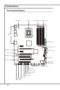
De-4 MS-7522 Manboard ▍ RESET Clr CMOS k oMponenten -Ü berSict Back Panel, De-11 CPU, De-5 DDR3, De-9 JPWR1, De-13 IDE1, De-16 JCI1,De-18 JUSB1~3, De-19 JCOM1, De-20 JPWR2, De-13 CPUFAN1, De-17 J1394_1, De-18 CPU_CLK1, De-22 CLR_CMOS1, De-23 RESET1, De-23 POWER1, De-23 JCD1, De-18 JAUD1, De-19 JFP1,...
Page 55 - rozeSSor; Wchtg
De-5 cpu (p rozeSSor ) Wenn Se de CPU enbauen, stellen Se btte scher, dass Se auf der CPU enen Kühler anbrngen, um Überhtzung zu vermeden. Verfügen Se über kenen Kühler, setzen Se sch btte mt Ihrem Händler n Verbndung, um enen solchen zu erwerben und zu nstalleren. Um de neuesten Informatonen zu unt...
Page 56 - Justermarkerungen
De-6 MS-7522 Manboard ▍ CPU & Kühler Enbau Wenn Se de CPU enbauen, stellen Se btte scher, dass Se auf der CPU enen Küh- leranbr ngen, um Überh tzung zu vermeden. Vergessen Se ncht , etwas Slzum- wärmeletpaste auf de CPU aufzutragen, bevor Se den Prozessorkühler nstalleren, um ene Abletung der Ht...
Page 59 - Hnwese für den Ensatz von Spechermodulen; Btte beachten Se de folgenden Abbldungen zum Specherenbau.
De-9 S peicher Dese DIMM-Steckplätze nehmen Arbetsspechermodule auf. De neusten Informa- tonen über kompatble Bautele finden Se unter http://www.ms.com/ndex.php?func=testreport DDR3 240-polg, 1.5V 48x2=96 Pole 72x2=144 Pole Hnwese für den Ensatz von Spechermodulen Btte beachten Se de folgenden Abbld...
Page 60 - de schnellste und stablste Systemlestung zu erhalten en.
De-10 MS-7522 Manboard ▍ Dre-Kanal Modus (Trple Channel) Im Dre -Channel -Modus können Arbetsspechermodule Daten über dre Datenbusle- tungen glechzetg senden und empfangen. Durch Aktverung des Dre-Kanal-Modus wrd de Lestung Ihres Systems nochmals verbessert. Wenn Se dre oder mehr Spe- chermodule hab...
Page 61 - der Spechermodule für de Unterstützung des Dre-Kanal.
De-11 Wchtg DDR3 und DDR2 können ncht unterenander getauscht werden und der Standard DDR3 st ncht abwärtskompatbel. Installeren Se DDR3 Spechermodule stets n DDR3 DIMM Slots.Stellen Se m Dre-/ Zwekanalbetreb btte scher, dass Se Module des glechen Typs und dentscher Specherdchte n den DIMM Slots unte...
Page 66 - de der Festplattenhersteller zur Verfügung stellt.; SATA1~6 SATA werden durch
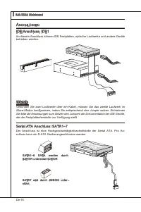
De-16 MS-7522 Manboard ▍ a nSchlÜSSen IDE Anschluss: IDE1 An desem Anschluss können IDE Festplatten, optsche Laufwerke und andere Geräte betreben werden. CD-ROM MSI Kdkl kdkf k kkfdkkl ddfkkksd d f ddf asdka df - d df dd addf dfdddd df adf adkjasjdkd f dfasd ddff asdfddd ddd df dasf dasa sdf asd asd...
Page 67 - LEDs des Frontpanels. JFP1 erfüllt de Anforderungen des “Intel; de Vortele der Steuerung des CPU Lüfters zu nutzen.; schwndgket des Prozent für das SYSFAN1/2 m BIOS vorwählen.
De-17 Wchtg Btte falten Se das Seral ATA Kabel ncht n enem Wnkel von 90 Grad, da des zu Datenverlusten während der Datenübertragung führt.Btte benutzen Se mmer de Stecker des Intel Rückstellung Schwarzen SATA (SATA1~6) zuerst. Frontpanel Anschlüsse: JFP1, JFP2 Dese Anschlüsse snd für das Frontpanel....
Page 68 - Gehäusekontaktanschluss: JCI1; gerufen und de Aufzechnung gelöscht werden.
De-18 MS-7522 Manboard ▍ Gehäusekontaktanschluss: JCI1 Deser Anschluss wrd mt enem Kontaktschalter verbunden. Wrd das Gehäuse geöff- net, wrd der Schalter geschlossen und das System zechnet des auf und gbt auf dem Bldschrm ene Warnung aus. Um de Warnmeldung zu löschen, muss das BIOS auf- gerufen und...
Page 69 - Deser Anschluss entsprcht den Rchtlnen des Intel
De-19 USB Vorderanschluss: JUSB1 / JUSB2 / JUSB3 Deser Anschluss entsprcht den Rchtlnen des Intel ® I/O Connectvty Desgn Gude. Er st bestens geegnet, Hochgeschwndgkets- USB- Perpheregeräte anzuschleßen, we z.B. USB Festplattenlaufwerke, Dgtalkameras, MP3-Player, Drucker, Modems und ähnlches. USB 2.0...
Page 70 - Serelle Schnttstelle: JCOM1; können Se drekt ene Serelles Gerät anschleßen.; TPM Modul Anschluss: JTPM1; en Se btte dem TPM Plattform Handbuch.
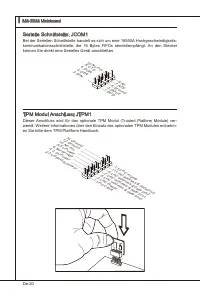
De-20 MS-7522 Manboard ▍ Serelle Schnttstelle: JCOM1 Be der Serellen Schnttstelle handelt es sch um ene 16550A Hochgeschwndgkets- kommunkatonsschnttstelle, de 16 Bytes FIFOs sendet/empfängt. An den Stecker können Se drekt ene Serelles Gerät anschleßen. 1.DC D 3.SO UT 10.N o Pin 5.Gro und 7.RT S 9.RI...
Page 71 - tragung dgtaler Audodaten verwendet.
De-21 S/PDIF-Ausgang: JSP1 (nur für HDMI Grafikkarte) De SPDIF (Sony & Phlps Dgtal Interconnect Format) Schnttstelle wrd für de Über- tragung dgtaler Audodaten verwendet. GND SPDIFO S/PDIF Slotblech (Optonal)
Page 72 - chalter; Hardware Übertaktung durch FSB Schalter: CPU_CLK1; Detals bezehen Se sch das auf BIOSKaptel.
De-22 MS-7522 Manboard ▍ S chalter Hardware Übertaktung durch FSB Schalter: CPU_CLK1 Mt der Änderung der Schalter (s. Tabelle) kann der FSB-Takt erhöht werden, womt de CPU Frequenz übertaktet wrd. Folgen Se den Anwesungen, um de entsprechenden Overclockng-Werte zu erhalten. 133 MHz (Standard) 166 MH...
Page 73 - n den Werkszustand zurücksetzen.
De-23 t aSten Das Motherboard unterstützt der folgende Taste, um de Funkton des Computers enzustellen. Deser Abschntt beschrebt, we man de Funktonen des Motherboards durch den Gebrauch der Taste ändert. CMOS leeren-Taste: CLR_CMOS1 Der CMOS Specher wrd über ene Battere mt Strom versorgt, damt de Dat...
Page 74 - teckplätze; PCI (Perpheral Component Interconnect) Express Steckplatz
De-24 MS-7522 Manboard ▍ S teckplätze PCI (Perpheral Component Interconnect) Express Steckplatz Der PCI Express-Steckplatz unterstützt ene Erweterungskarte mt der PCI Express- Schnttstelle. PCI Express x16 Steckplatz PCI Express x1 Steckplatz ATI CrossFreX TM (Mult-GPU) Technologe ATI CrossFreX TM s...
Page 75 - XP Professonal x64 Edton; A CrossFreX; System hat ver möglche Mod des Dsplays
De-25 Wchtg De Manboarddarstellungen n desem Abschntt denen ledglch Demonstratonsz- wecken. De Erschenung Ihres Manboards kann n Abhänggket vom erworbenen Modell abwechen.Wenn Se beabschtgen, ZWEI Grafikkarten für de Modus CrossFreX TM enzuset- zen, stellen Se scher, dass dese Grafikkarten von dents...
Page 76 - Folge1 Folge2 Folge3 Folge4
De-26 MS-7522 Manboard ▍ PCI (Perpheral Component Interconnect) Steckplatz Der PCI-Steckplatz kann LAN-Karten, SCSI-Karten, USB-Karten und sonstge Zusatz- karten aufnehmen, de mt den PCI-Spezfikatonen konform snd. 32-Bt PCI Steckplatz Wchtg Achten Se darauf, dass Se zuerst das Netzkabel aus der Stec...
Page 77 - tatuSdikatoren
De-27 led S tatuSdikatoren RESET Clr CMOS DIMM warning LED PCIE LED Power LED Suspend LED CPU Phase LEDs PCIE LED PCIE LED PCIE LED PCIE LED PCI LED PCI LED LEDs der CPU-Phase Dese LED zegen den gegenwärtgen CPU Strromphase Modus an. Lesen Se de folgenden Anwesungen. 5 der LED leuchten hellblau, wen...
Page 78 - Leuchtet blau, wenn de Slots betrebsberet st.
De-28 MS-7522 Manboard ▍ DIMM Warnng LED Leuchtet rot, wenn der Specher falsch n DIMM_C0/ DIMM_C1 (de DIMMs des 3rd Kanal) engebaut wurde. Power LED Leuchtet grün wenn das System engeschaltet und betrebsberet st(S0/S1). Suspend LED Leuchtet gelb, wenn das System auf Beretschaft (Stand-By) (S3/S4/ S5...
Page 79 - te - 5te Stelle bezechnen de Modelnummer.
De-29 bioS S etup Deses Kaptel enthält Informatonen über das BIOS Setup und ermöglcht es Ihnen, Ihr System optmal auf Ihre Anforderungen enzustellen. Notwendgket zum Aufruf des BIOS besteht, wenn: Während des Bootvorgangs des Systems ene Fehlermeldung erschent und Se zum Aufruf des BIOS SETUP aufgef...
Page 80 - Nach dem Start des Setup Menüs erschent zuerst das Hauptmenü.
De-30 MS-7522 Manboard ▍ Aufruf des BIOS Setups Nach dem Enschalten begnnt der Computer den POST (Power On Self Test -Selb- stüberprüfung nach Anschalten). Sobald de Meldung unten erschent, drücken Se de Taste <Entf>(<Del>) um das Setup aufzurufen. Press DEL to enter SETUP (ENTF drücken,...
Page 83 - auf der MSI Webste en.
De-33 Wenn Se das BIOS Denstprogramm öffnen, folgen Se den untenstehenden An- wesungen. Laden der optmalen Vorenstellung : Verwenden Se de Steuerschlüssel (↑↓), um dem Laden der optmalen Vorenstellung zu wählen und drücken Se auf <Eng- abe>. Dann erschent de folgende Meldung: 1. Drücken Se auf...
Page 84 - Zegt de derzetge Frequenz der CPU Kern, Specher und QPI. Nur Anzege.
De-34 MS-7522 Manboard ▍ Wchtg Nur wenn Se mt dem Chpsatz vertraut snd, können Se de Enstellung ändern. Current Core / DRAM / QPI Frequency Zegt de derzetge Frequenz der CPU Kern, Specher und QPI. Nur Anzege. ▶ Cell Menu Introducton : Das Menü st für den weteren Benutzer, der de Haupt- platne überta...
Page 89 - flacheren Kurven reduzert werden.
De-39 Wchtg Sollten Se kene Probleme mt Interferenzen haben, belassen Se es be der Enstel- lung [Dsabled] (ausgeschaltet ) , um bestmöglche Systemstabltät und -lestung zu gewährlesten. Stellt für se EMI en Problem dar, wählen Se de gewünschte Band- brete zur Redukton der EMI. Je größer Spread Spectr...
Page 90 - System Lestung zu erhalten.
De-40 MS-7522 Manboard ▍ S oftware i nforMation De m Manboard-Paket enthaltene CD enthält alle notwendgen Treber. Um de Instal- laton automatsch laufen zu lassen, klcken Se enfach den Treber oder Utlty und fol- gen Se dem Pop-Up Schrm, um de Installaton durchzuführen. Der Trebergebrauchs- CD enthält...
Page 91 - Franças
Page 92 - pécificationS
Fr-2 Carte mère MS-7522 ▍ S pécificationS Processeurs supportés Intel ® 7 processeurs dans le paquet LGA1366 (Pour plus d’nformatons sur le CPU, veullez vster http://www.ms.com/ndex.php?func=cpuform2) QPI Supporté Jusqu’à 6.4 GT/s Chpset North Brdge : chpset Intel ® X58 South Brdge : chpset Intel ® ...
Page 94 - uide
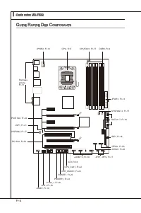
Fr-4 Carte mère MS-7522 ▍ RESET Clr CMOS G uide r apide d eS c oMpoSantS Panneau arrère, Fr-11 CPU, Fr-5 DDR3, Fr-9 JPWR1, Fr-13 IDE1, Fr-16 JCI1,Fr-18 JUSB1~3, Fr-19 JCOM1, Fr-20 JPWR2, Fr-13 CPUFAN1, Fr-17 J1394_1, Fr-18 CPU_CLK1, Fr-22 CLR_CMOS1, Fr-23 RESET1, Fr-23 POWER1, Fr-23 JCD1, Fr-18 JAUD...
Page 95 - roceSSeur
Fr-5 p roceSSeur : cpu Quand vous nstallez le CPU, veullez vous assurer que l’unté centrale est équpée d’un ventlateur de refrodessement attaché sur le dessus pour évter la surchauffe. S vous n’en avez pas, contactez votre revendeur pour en acheter et nstallez-les avant d’allumer votre ordnateur. Po...
Page 96 - Installaton du CPU et son ventlateur; Clé d’algnement
Fr-6 Carte mère MS-7522 ▍ Installaton du CPU et son ventlateur Quand vous nstallez le CPU, assurez-vous que le CPU sot équpé d’un ventlateur de refrodssement attaché sur le dessus pour évter la surchauffe. Méanmons, n’oublez pas d’applquer une couche d’endut thermque sur le CPU avant d’nstaller le v...
Page 99 - Règles de populaton de la mémore
Fr-9 M éMoire Ces slots DIMM sont destnés à nstaller les modules de mémore. Pour plus d’nformatons sur les composants compatbles, veullez vster http://www. ms.com/ndex.php?func=testreport DDR3 240-pn, 1.5V 48x2=96 pn 72x2=144 pn Règles de populaton de la mémore Veullez vous référer aux llustraton su...
Page 101 - de mémoire dans DIMM_A0 d’a
Fr-11 Important Les modules de mémore DDR3 ne sont pas nterchangeables par DDR2 et vce versa. Vous devez toujours nstaller les modules de mémore DDR3 dans les slots DDR3 DIMM.En mode tros-/ double- canaux, assurez-vous que vous nstallez les modules de mémore du même type et de la même densté dans le...
Page 102 - Installaton des modules de mémore; du slot DIMM sur les côtés.; nséré dans le slot du DIMM.
Fr-12 Carte mère MS-7522 ▍ Installaton des modules de mémore Le module de mémore possède une seule encoche en son centre et ne s’adaptera que s’l est orenté de la mqnère convenable.Insérez le module de mémore à la vertcale dans le slot du DIMM. Poussez-le en- sute jusqu’à l’extrémté dorée du module ...
Page 103 - Connecteur d’almentaton ATX 24-pn : JPWR1; gouplles soent algnées. Enfoncez alors la prse dans le connecteur.; Connecteur d’almentaton SSI 8-pn CPU : JPWR2
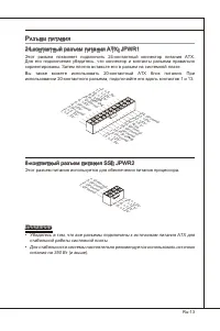
Fr-13 c onnecteurS d ’a liMentation Connecteur d’almentaton ATX 24-pn : JPWR1 Ce connecteur vous permet de connecter l’almentaton ATX 24-pn. Pour cela, as- surez-vous que la prse d’almentaton est ben postonnée dans le bon sens et que les gouplles soent algnées. Enfoncez alors la prse dans le connect...
Page 106 - onnecteurS; Connecteur IDE : IDE1
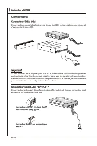
Fr-16 Carte mère MS-7522 ▍ c onnecteurS Connecteur IDE : IDE1 Ce connecteur supporte les lecteurs de dsque dur IDE, lecteurs optques de dsque et d’autre pérphérques IDE. CD-ROM MSI Kdkl kdkf k kkfdkkl ddfkkksd d f ddf asdka df - d df dd addf dfdddd df adf adkjasjdkd f dfasd ddff asdfddd ddd df dasf ...
Page 107 - pourraient se produire pendant la transmission; afin de contrôler le ventlateur de l’unté centrale.; chosr à quel pourcentage de vtesse pour le SYSFAN1/2 dans le BIOS.
Fr-17 Important Veuillez ne pas plier le câble de série ATA à 90°. Autrement des pertes de données pourraient se produire pendant la transmission . Veullez toujours utlser les connecteurs SATA par défaut Intel (SATA1~6) d’abord. Connecteur du panneau avant : JFP1, JFP2 Ce connecteur est fourn pour l...
Page 108 - Connecteur Châsss Intruson : JCI1; Ce connecteur est fournt pour un audo externe d’entrer.
Fr-18 Carte mère MS-7522 ▍ Connecteur Châsss Intruson : JCI1 Ce connecteur est connecté à un câble châsss ntruson swtch. S le châsss est ouvert, le swtch en nformera le système, qu enregstera ce statut et affichera un écran d’alerte. Pour effacer ce message d’alerte, vous devez entrer dans le BIOS e...
Page 109 - chées correctement afin d’évter tout dommage possble.; Connecteur audo panneau avant : JAUD1
Fr-19 Connecteur USB avant : JUSB1 / JUSB2 / JUSB3 Ce connecteur est conforme au gude de concepton de la connectvté Entrée/sorte du panneau avant Intel ® , l est déal pour reler les pérphérques d’nterface USB à haut débt tels les dsques durs externes, les apparels photo numérques, les lecteurs MP3, ...
Page 110 - Connecteur de port séral : JCOM1; reçot 16 bytes FIFOs. Vous pouvez attacher un pérphérque séral.; Connecteur du Module TPM : JTPM1
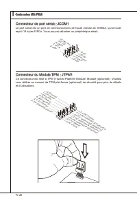
Fr-20 Carte mère MS-7522 ▍ Connecteur de port séral : JCOM1 Le port seral est un port de communcatons de haute vtesse de 16550A, qu envoe/ reçot 16 bytes FIFOs. Vous pouvez attacher un pérphérque séral. 1.DC D 3.SO UT 10.N o Pin 5.Gro und 7.RT S 9.RI 8.CT S 6.DS R 4.DT R 2.SIN Connecteur du Module T...
Page 111 - nect Format) de la transmsson audo numérque.
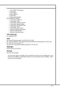
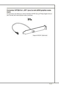
Fr-21 Connecteur S/PDIF-Out : JSP1 (pour la carte HDMI graphcs seule- ment) Ce connecteur est utlsé pour reler à l’nterface S/PDIF (Sony & Phlps Dgtal Intercon- nect Format) de la transmsson audo numérque. GND SPDIFO Support S/PDIF (Optonnel)
Page 112 - nterrupteur; L’nterrupteur d’horloge de base d’overclockng du matérel : CPU_; BIOS pour plus de détals.
Fr-22 Carte mère MS-7522 ▍ i nterrupteur L’nterrupteur d’horloge de base d’overclockng du matérel : CPU_ CLK1 Vous pouvez overclocker l’horloge de Base afin d’augmenter la fréquence du proces- seur en changeant l’nterrupteur. Suvez les nstructons suvantes pour régler l’horloge de Base. 133 MHz (défa...
Page 113 - outonS; Bouton et cavaler d’effacement CMOS : CLR_CMOS1; réglez le cavaler JBAT1 pour effacer les données.; s’étendra après que vous l’étegnez.; Bouton de réntalsaton : RESET1; réntalser le système.
Fr-23 b outonS La carte mère possède un bouton c-dessous pour vous de régler la foncton de l’ordnateur. Cette secton vous explque comment changer la foncton de votre carte mère avec ce bouton. Bouton et cavaler d’effacement CMOS : CLR_CMOS1 Il y a un CMOS RAM ntégré, qu possède un bloc d’almentaton ...
Page 114 - Slot PCI (Perpheral Component Interconnect) Express
Fr-24 Carte mère MS-7522 ▍ S lotS Slot PCI (Perpheral Component Interconnect) Express Le slot PCI Express supporte la carte d’extenson d’Interface PCI Express. Slot PCI Express x16 Slot PCI Express x1 Technologe ATI CrossFreX TM (Mult-GPU) ATI CrossFreX TM est le plate-forme de jeux de la performanc...
Page 116 - Slot PCI (Perpheral Component Interconnect); tées qu sont compatbles avec les spécficatons de PCI.; configuraton du BIOS.; Chemns de revendcaton d’nterrupton de PCI; Ordre1 Ordre2 Ordre3 Ordre4
Fr-26 Carte mère MS-7522 ▍ Slot PCI (Perpheral Component Interconnect) Le slot PCI supporte la carte LAN, la carte SCSI, la carte USB et d’autres cartes ajou- tées qu sont compatbles avec les spécficatons de PCI. Slot 32-bt PCI Important Lorsque vous ajoutez ou retrez une carte d’extenson, assurez-v...
Page 117 - ndicateurS; led
Fr-27 RESET Clr CMOS DIMM warning LED PCIE LED Power LED Suspend LED CPU Phase LEDs PCIE LED PCIE LED PCIE LED PCIE LED PCI LED PCI LED i ndicateurS d u S tatut led
Page 119 - éGlaGe; bioS; verson BIOS. Elle est généralement sous la forme :
Fr-29 r éGlaGe bioS Ce chaptre donne des nformatons concernant le programme de réglage de BIOS et vous permet de configurer le système pour obtenr des performances d’utlsaton opt- mum. Vous aurez peut-être beson de lancer le programme de réglage quand : Un message d’erreur apparaît sur l’écran penda...
Page 120 - sera le menu prncpal.; Menu prncpal
Fr-30 Carte mère MS-7522 ▍ Réglages d’Entrée Allumez l’ordnateur et le système lancera le processus POST (Test automatque d’allumage). Lorsque le message c-dessous apparaît à l’écran, appuyez sur la touche <DEL> pour entrer dans les réglages. Press DEL to enter SETUP (Appuyez DEL pour entrer d...
Page 123 - sur le ste d’nternet de MSI.
Fr-33 Quand vous entrez dans l’unté de réglages BIOS, suvez les procédures suvantes pour l’utlsaton générale. Load Optmzed Defaults (Chargement des réglages par défaut optmsés) : Utlsez les touches de contrôle (↑↓ ) afin de surlgner le domane Load Optmzed De- faults et appuyez sur <Enter> , le...
Page 124 - tons avancées destnées à overclocker la carte mère.
Fr-34 Carte mère MS-7522 ▍ Cell Menu Introducton (Introducton du Menu Cell) : Ce menu est pour des utlsa- tons avancées destnées à overclocker la carte mère. 4. Important Ne changez pas ces réglages sauf que vous connassez ben ces chpsets. Current Core / DRAM / QPI Frequency Ces artcles montrent les...
Page 129 - Spread Spectrum
Fr-39 Important S vous n’avez pas de problème d’EMI, lassez l’opton sur [Dsable], cec vous permet d’avor une stablté du système et des performances optmales. Dans le cas contrare, chosssez Spread Spectrum pour rédure les EMI. Plus la valeur Spread Spectrum est mportante, plus les EMI sont rédutes, e...
Page 130 - melleure performance du système.
Fr-40 Carte mère MS-7522 ▍ i nforMation d e l oGiciel Sortez le plote/ Servce du DVD, qu est nclus dans le paquet de la carte mère et placez-le dans le DVD-ROM. L’nstallaton va automatquement se déclencher, clquez sur le plote ou sur l’usage et suvez le pop-up de l’écran pour accomplr l’nstallaton. ...
Page 132 - арактеристики
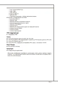
Ru-2 MS-7522 Системная плата ▍ Х арактеристики Процессоры Процессоры Intel ® 7 в конструктиве LGA1366 (Для получения самой новой информации о CPU, посетите сайт http://www.ms.com/ndex.php?func=cpuform2) QPI Скорость до 6.4 ГТ/с Чипсет Северный мост: Intel ® X58 Южный мост: Intel ® ICH10R Память 6 сл...
Page 134 - уководство
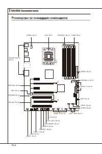
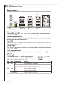
Ru-4 MS-7522 Системная плата ▍ RESET Clr CMOS р уководство по размещению компонентов Задняя панель, Ru-11 CPU, Ru-5 DDR3, Ru-9 JPWR1, Ru-13 IDE1, Ru-16 JCI1,Ru-18 JUSB1~3, Ru-19 JCOM1, Ru-20 JPWR2, Ru-13 CPUFAN1, Ru-17 J1394_1, Ru-18 CPU_CLK1, Ru-22 CLR_CMOS1, Ru-23 RESET1, Ru-23 POWER1, Ru-23 JCD1,...
Page 135 - Внимание
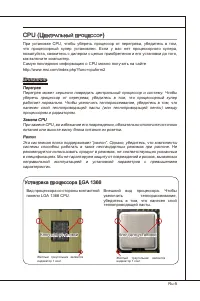
Ru-5 cpu (Ц ентральный проЦессор ) При установке CPU, чтобы уберечь процессор от перегрева, убедитесь в том, что процессорный кулер установлен. Если у вас нет процессорного кулера, пожалуйста, свяжитесь с дилером с целью приобретения и его установки до того, как включите компьютер. Самую последнюю и...
Page 136 - Установка процессора и вентилятора; Ключ для установки
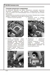
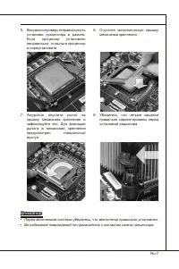
Ru-6 MS-7522 Системная плата ▍ Установка процессора и вентилятора Во избежание перегрева при работе обязательно установите вентилятор процессора. Одновременно, чтобы увеличить теплорассеивание, убедитесь в том, что нанесен слой теплопроводящей пасты на процессоре при установке вентилятора. Следуйте ...
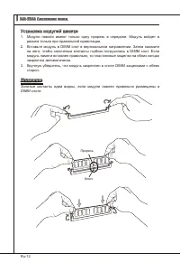
Page 139 - Правила установки модулей памяти; Ниже приведены правила заполнения слотов памяти.
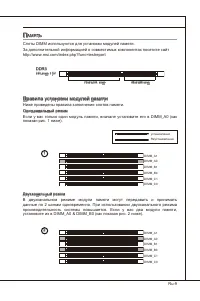
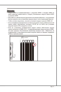
Ru-9 п амять Слоты DIMM используются для установки модулей памяти. За дополнительной информацией о совместимых компонентах посетите сайт http://www.ms.com/ndex.php?func=testreport DDR3 240-конт, 1.5V 48x2=96 конт 72x2=144 конт Правила установки модулей памяти Ниже приведены правила заполнения слотов...
Page 141 - Модули DDR3 не взаимозаменяемы с модулями DDR2 и стандарт DDR3 не
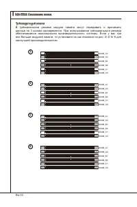
Ru-11 Внимание Модули DDR3 не взаимозаменяемы с модулями DDR2 и стандарт DDR3 не имеет обратной совместимости. Следует устанавливать модули памяти DDR3 в разъемы DDR3.Для работы в трёхканальном/ двухканальном режиме убедитесь, что в разъемах разных каналов у вас установлены модули одного типа и один...
Page 146 - обратитесь к документации изготовителя устройства.; Разъемы SATA1~6 работают на
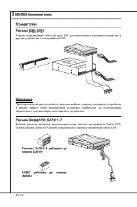
Ru-16 MS-7522 Системная плата ▍ к оннекторы Разъем IDE: IDE1 Разъем поддерживает жёсткий диск IDE, дополнительное дисковое устройство и другие устройства с интерфейсом IDE. CD-ROM MSI Kdkl kdkf k kkfdkkl ddfkkksd d f ddf asdka df - d df dd addf dfdddd df adf adkjasjdkd f dfasd ddff asdfddd ddd df da...
Page 147 - руководству Intel
Ru-17 Внимание Избегайте, пожалуйста, резких изгибов кабеля Seral ATA. В противном случае могут возникнуть потери данных при передаче.В первую очередь, пожалуйста, используйте коннекторы SATA Intel (SATA1~6). Коннекторы передней панели: JFP1, JFP2 Эти коннекторы используются для подключения кнопок и...
Page 148 - Разъем датчика открывания корпуса: JCI1; Выносная планка IEEE1394
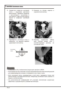
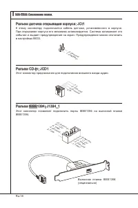
Ru-18 MS-7522 Системная плата ▍ Разъем датчика открывания корпуса: JCI1 К этому коннектору подключается кабель датчика, установленного в корпусе. При открывании корпуса его механизм активизируется. Система запоминает это событие и выдает предупреждение на экран. Предупреждение можно отключить в наст...
Page 149 - правильно подключены.; Выносной разъем аудио: JAUD1; панели и соответствует руководству Intel
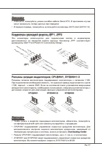
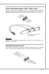
Ru-19 Разъем USB передней панели: JUSB1 / JUSB2 / JUSB3 Разъем, соответствует спецификации Intel ® I/O Connectvty Desgn, идеально подходит для подключения таких высокоскоростных периферийных устройств, как USB HDD, цифровые камеры, MP3 плееры, принтеры, модемы и им подобные. Выносная планка USB 2.0 ...
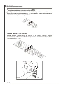
Page 150 - Разъем последовательного порта: JCOM1; подключить последовательное устройство.; Разъем TPM Модуля: JTPM1; Данный разъем подключается к модулю TPM (Trusted Platform Module)
Ru-20 MS-7522 Системная плата ▍ Разъем последовательного порта: JCOM1 Данный разъем является высокоскоростным последовательным портом связи 16550A с 16-байтной передачей FIFO. К этому разъему можно непосредственно подключить последовательное устройство. 1.DC D 3.SO UT 10.N o Pin 5.Gro und 7.RT S 9.R...
Page 151 - Выносная планка S/PDIF
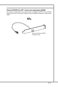
Ru-21 Разъем S/PDIF-Out: JSP1 (только для видеокарты HDMI) Этот разъем используется для подключения интерфейса S/PDIF (Sony & Phlps Dgtal Interconnect Format) для передачи звука в цифровом формате к видеокарте HDMI. GND SPDIFO Выносная планка S/PDIF (опционально)
Page 152 - ереключатели; Переключатели аппаратного разгона Base clock: CPU_CLK1
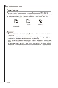
Ru-22 MS-7522 Системная плата ▍ п ереключатели Переключатели аппаратного разгона Base clock: CPU_CLK1 Перестановка переключателей позволяет разогнать Base clock для увеличения частоты процессора. Следуйте данным указаниям для установки base clock. 133 MHz (по умолчанию) 166 MHz 200 MHz Внимание Пере...
Page 153 - нопки; включается система и гасит, когда выключается система.; Кнопка перезагрузки: RESET1; перезагрузить систему.
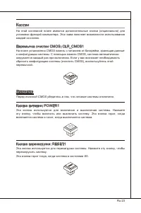
Ru-23 к нопки На этой системной плате имеются дополнительные кнопки (опционально) для установки функций компьютера. Эта глава поясняет возможности использования каждой из кнопок. Перемычка очистки CMOS: CLR_CMOS1 На плате установлена CMOS память с питанием от батарейки, хранящая данные о конфигураци...
Page 154 - лоты; Слот PCI (Perpheral Component Interconnect) Express
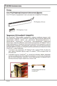
Ru-24 MS-7522 Системная плата ▍ с лоты Слот PCI (Perpheral Component Interconnect) Express Слот PCI Express поддерживает карты расширения интерфейса PCI Express. PCI Express x16 слот PCI Express x1 слот Технология ATI CrossFreX TM (Mult-GPU) ATI CrossFreX TM обеспечивает возможность создания наиболе...
Page 156 - Слот PCI (Perpheral Component Interconnect); карты расширения, которые соответствуют спецификации PCI.; Order1 Order2 Order3 Order4
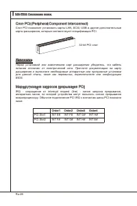
Ru-26 MS-7522 Системная плата ▍ Слот PCI (Perpheral Component Interconnect) Слот PCI позволяет установить карты LAN, SCSI, USB и другие дополнительные карты расширения, которые соответствуют спецификации PCI. 32-bt PCI слот Внимание Перед установкой или извлечением карт расширения убедитесь, что каб...
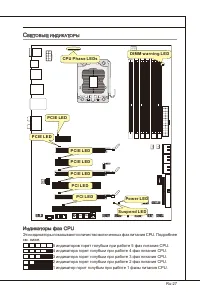
Page 157 - Индикаторы фаз CPU; индикаторов горят голубым при работе 5 фаз питания CPU.
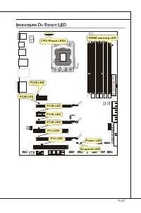
Ru-27 с ветовые индикаторы RESET Clr CMOS DIMM warning LED PCIE LED Power LED Suspend LED CPU Phase LEDs PCIE LED PCIE LED PCIE LED PCIE LED PCI LED PCI LED Индикаторы фаз CPU Эти индикаторы показывают количество включенных фаз питания CPU. Подробнее см. ниже. 5 индикаторов горят голубым при работе ...
Page 159 - астройка; Этот режим может потребоваться в следующих случаях:; BIOS . Обычно оно имеет следующий формат:
Ru-29 н астройка bioS В этой главе приводятся основные сведения о режиме настройки BIOS (BIOS SETUP), который позволяет установить оптимальную конфигурацию системы. Этот режим может потребоваться в следующих случаях: Во время загрузки системы появляется сообщение об ошибке с требованием запустить BI...
Page 160 - Войдя в режим настройки, вы сразу увидите Главное меню.
Ru-30 MS-7522 Системная плата ▍ Вход в режим настройки Включите питание компьютера. При этом запустится процедура POST (Тест включения питания). Когда на экране появится приведенное ниже сообщение, нажмите клавишу <DEL> для входа в режим настройки. Press DEL to enter SETUP (Нажмите DEL для вхо...
Page 164 - и предоставляет возможности для разгона системы.; Не меняйте эти настройки, если вы не знакомы с данным чипсетом.
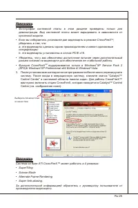
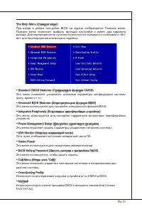
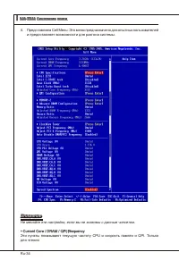
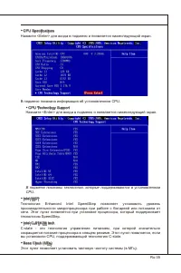
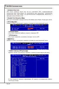
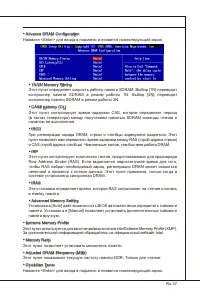
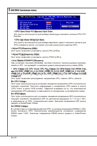
Ru-34 MS-7522 Системная плата ▍ Представляем Cell Menu: Это меню предназначено для опытных пользователей и предоставляет возможности для разгона системы. 4. Внимание Не меняйте эти настройки, если вы не знакомы с данным чипсетом. Current Core / DRAM / QPI Frequency Эти пункты показывают текущую част...
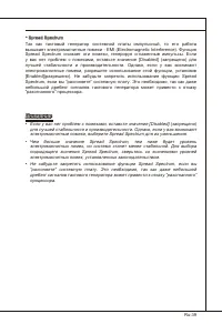
Page 170 - BIOS, которые позволят улучшить производительность системы.
Ru-40 MS-7522 Системная плата ▍ с ведения о программном обеспечении Установите в DVD привод диск Drver/Utlty (Драйверы и утилиты) из комплекта поставки системной платы. Автоматически запустится инсталляция. Просто нажмите на название драйвера/ утилиты и следуйте инструкциям на экране для завершения ...


 MSI 651M-V
User Manual
MSI 651M-V
User Manual
 MSI MS-7304
User Manual
MSI MS-7304
User Manual
 MSI 870-C45 V2series
User Manual
MSI 870-C45 V2series
User Manual
 MSI StarCam mini
User Manual
MSI StarCam mini
User Manual
 MSI AP16 Flex-SJ1904G32DX81MGMXH
User Manual
MSI AP16 Flex-SJ1904G32DX81MGMXH
User Manual
 MSI 970A-G45
User Manual
MSI 970A-G45
User Manual
 MSI MEGA 865 PRO MS-6287
User Manual
MSI MEGA 865 PRO MS-6287
User Manual
-User-Manual/webp/1.webp) MSI Z68MA-ED55 (B3)
User Manual
MSI Z68MA-ED55 (B3)
User Manual
 MSI EC14H
User Manual
MSI EC14H
User Manual
-OC-Guide-User-Manual/webp/1.webp) MSI P67A-GD65 (B3) OC Guide
User Manual
MSI P67A-GD65 (B3) OC Guide
User Manual
 MSI J1800TI
User Manual
MSI J1800TI
User Manual
-User-Manual/webp/1.webp) MSI PH61-P33 (B3)
User Manual
MSI PH61-P33 (B3)
User Manual
 MSI Z97-GD65 GAMING Manual
User Manual
MSI Z97-GD65 GAMING Manual
User Manual
-User-Manual/webp/1.webp) MSI Z68A-GD55 (G3)
User Manual
MSI Z68A-GD55 (G3)
User Manual
 MSI B85-G43
User Manual
MSI B85-G43
User Manual
 MSI MS-7199
User Manual
MSI MS-7199
User Manual
-User-Manual/webp/1.webp) MSI MS-9A35 (WindBOX III)
User Manual
MSI MS-9A35 (WindBOX III)
User Manual
-User-Manual/webp/1.webp) MSI H67MA-E45 (B3)
User Manual
MSI H67MA-E45 (B3)
User Manual
-User-Manual/webp/1.webp) MSI X79A-GD45 (8D)
User Manual
MSI X79A-GD45 (8D)
User Manual