Page 3 - Safety Instructons
Preface ▍ MS-7581 Preface ▍ MS-7581 Safety Instructons Always read the safety nstructons carefully.Keep ths User’s Manual for future reference.Keep ths equpment away from humdty.Lay ths equpment on a relable flat surface before settng t up.The openngs on the enclosure are for ar convecton hence prot...
Page 4 - FCC-B Rado Frequency Interference Statement
v Preface ▍ MS-7581 Preface ▍ MS-7581 FCC-B Rado Frequency Interference Statement Ths equpment has been tested and found to comply wth the lmts for a Class B dg- tal devce, pursuant to Part 15 of the FCC Rules. These lmts are desgned to provde reasonable protecton aganst harmful nter- ference n a re...
Page 5 - WEEE (Waste Electrcal and Electronc Equpment) Statement; ENGLISH; schlesslch an ener lokalen Altgerätesammelstelle n Ihrer Nähe.; FRANÇAIS; эти изделия в специализированные пункты приема.
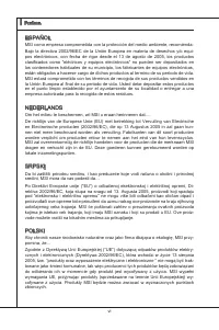
Preface ▍ MS-7581 v Preface ▍ MS-7581 WEEE (Waste Electrcal and Electronc Equpment) Statement ENGLISH To protect the global envronment and as an envronmentalst, MSI must remnd you that...Under the European Unon (“EU”) Drectve on Waste Electrcal and Elec- tronc Equpment, Drectve 2002/96/EC, whch take...
Page 6 - ESPAÑOL; empresa autorzada para la recogda de estos resduos.; NEDERLANDS; lokale nzamelngspunten.; SRPSKI; vode možete vratt na lokalnm mestma za prkupljanje.; POLSKI
v Preface ▍ MS-7581 Preface ▍ MS-7581 ESPAÑOL MSI como empresa comprometda con la proteccón del medo ambente, recomenda:Bajo la drectva 2002/96/EC de la Unón Europea en matera de desechos y/o equ- pos electróncos, con fecha de rgor desde el 13 de agosto de 2005, los productos clasficados como “eléct...
Page 7 - TÜRKÇE; noktalarına bırakablrsnz.; ČESKY; cclo d vta. È possble portare prodott nel pù vcno punto d raccolta
Preface ▍ MS-7581 v Preface ▍ MS-7581 TÜRKÇE Çevrec özellğyle blnen MSI dünyada çevrey korumak çn hatırlatır:Avrupa Brlğ (AB) Kararnames Elektrk ve Elektronk Malzeme Atığı, 2002/96/EC Kararnames altında 13 Ağustos 2005 tarhnden tbaren geçerl olmak üzere, elektrkl ve elektronk malzemeler dğer atıklar...
Page 8 - CONTENTS
v Preface ▍ MS-7581 Preface ▍ MS-7581 CONTENTS Copyrght Notce ............................................................................................ Trademarks .................................................................................................... Revson Hstory.......................
Page 11 - Seres; Englsh; Europe verson
Page 15 - Important
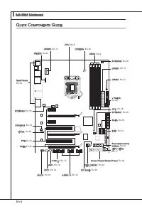
En-5 Englsh cpu (c entral p roceSSinG u nit ) When you are nstallng the CPU, make sure to nstall the cooler to prevent overheatng. If you do not have the CPU cooler, consult your dealer before turnng on the computer. For the latest nformaton about CPU, please vst http://www.ms.com/ndex. php?func=cpu...
Page 16 - CPU & Cooler Installaton; Algnment Key
En-6 MS-7581 Manboard ▍ CPU & Cooler Installaton When you are nstallng the CPU, make sure the CPU has a cooler attached on the top to prevent overheatng. Meanwhle, do not forget to apply some thermal paste on CPU before nstallng the heat snk/cooler fan for better heat dsperson. Follow the steps ...
Page 19 - Memory Populaton Rule; Dual-Channel mode Populaton Rule
En-9 Englsh M eMory These DIMM slots are used for nstallng memory modules. For more nformaton on compatble components, please vst http://www.ms.com/ndex.php?func=testreport DDR3 240-pn, 1.5V 48x2=96 pn 72x2=144 pn Memory Populaton Rule Please refer to the followng llustratons for memory populaton ru...
Page 20 - Installng Memory Modules
En-10 MS-7581 Manboard ▍ Installng Memory Modules The memory module has only one notch on the center and wll only fit n the rght orentaton.Insert the memory module vertcally nto the DIMM slot. Then push t n untl the golden finger on the memory module s deeply nserted n the DIMM slot. The plastc clp ...
Page 24 - onnectorS; suppled by the vendors for jumper settng nstructons.
En-14 MS-7581 Manboard ▍ c onnectorS IDE Connector: IDE1 Ths connector supports IDE hard dsk drves, optcal dsk drves and other IDE de- vces. CD-ROM MSI Kdkl kdkf k kkfdkkl ddfkkksd d f ddf asdka df - d df dd addf dfdddd df adf adkjasjdkd f dfasd ddff asdfddd ddd df dasf dasa sdf asd asd asdddddddfas...
Page 25 - occur durng transmsson.; Chasss Intruson Connector: JCI1; BIOS utlty and clear the record.
En-15 Englsh Seral ATA Connector: SATA1~8 Ths connector s a hgh-speed Seral ATA nterface port. Each connector can connect to one Seral ATA devce. Floppy D MSIFloppy D MSI Kdkl kdkf k kkfdkkl ddf kkksd d f ddf asdka df - d df dd addf df dddd dfadf adkjasjdkdf df asd ddff asdfdd dddd df dasfdasas df a...
Page 26 - CPUFAN
En-16 MS-7581 Manboard ▍ Fan Power Connectors: CPUFAN,SYSFAN1~4 The fan power connectors support system coolng fan wth +12V. When connectng the wre to the connectors, always note that the red wre s the postve and should be con- nected to the +12V; the black wre s Ground and should be connected to GN...
Page 27 - Buzz
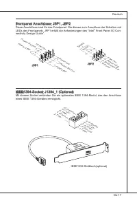
En-17 Englsh Front Panel Connectors: JFP1, JFP2 These connectors are for electrcal connecton to the front panel swtches and LEDs. The JFP1 s complant wth Intel ® Front Panel I/O Connectvty Desgn Gude. 1.Gro und 3.Su spen d LE D 5.Po wer L ED 7.No Pin 8.+ 6.- 4.+ 2.- Buzz er Spea ker 1.+ 3.- 10.N o P...
Page 28 - Ths connector, complant wth Intel
En-18 MS-7581 Manboard ▍ Front USB Connector: JUSB1 / JUSB2 / JUSB3 Ths connector, complant wth Intel ® I/O Connectvty Desgn Gude, s deal for con- nectng hgh-speed USB nterface perpherals such as USB HDD, dgtal cameras, MP3 players, prnters, modems and the lke. USB 2.0 Bracket (optonal) 10.U SBO C 8...
Page 29 - Front Panel Audo Connector: JAUD1
En-19 Englsh S/PDIF-Out Connector: JSP1 Ths connector s used to connect S/PDIF (Sony & Phlps Dgtal Interconnect Format) nterface for dgtal audo transmsson. 1.VC C 2.SP DIF 3.Gro und S/PDIF Bracket (Optonal) Front Panel Audo Connector: JAUD1 Ths connector allows you to connect the front panel aud...
Page 32 - the system s n regular operaton state.
En-22 MS-7581 Manboard ▍ b utton The motherboard provdes the followng buttons for you to set the computer’s functon. Ths secton wll explan how to change your motherboard’s functon through the use of button. Clear CMOS Button: CLR_CMOS1 There s a CMOS RAM on board that has a power supply from externa...
Page 33 - OC Gene Button: OC Gene; system wll restore the default for next boot.
En-23 Englsh OC Gene Button: OC Gene Ths button s used to auto-overclock for the system. Press ths button to enable the OC Gene functon when the system s n power off state, meanwhle, the button wll lght and lock. And then the system wll automatcally detect the optmum values to overclock after bootng...
Page 34 - system wll swtch the LED between on and off mode.
En-24 MS-7581 Manboard ▍ Power On Button: POWER Ths button s used to turn-on or turn-off the system. Press the button to turn-on or turn- off the system. Reset Button: RESET Ths button s used to reset the system. Press the button to reset the system. Important If you want to press ths button to rese...
Page 35 - witch
En-25 Englsh S witch Ths manboard provdes the followng swtch for you to set the computer’s functon. Ths secton wll explan how to change your manboard’s functon through the use of swtch. Over-Voltage Swtch: V Swtch You can ncrease the voltage range of CPU / CPU_VTT/ Memory/ PCH for adjustment n BIOS ...
Page 37 - PCIE (Perpheral Component Interconnect Express) Slot; PCI Express x16 Slot
En-27 Englsh S lotS PCIE (Perpheral Component Interconnect Express) Slot The PCI Express slot supports the PCI Express nterface expanson card. PCI Express x16 Slot PCI Express x1 Slot Important When addng or removng expanson cards, make sure that you unplug the power sup- ply first. Meanwhle, read t...
Page 40 - NVIDIA; graphcs card to ensure stable operaton of the graphcs card.
En-30 MS-7581 Manboard ▍ NVIDIA ® SLI Technology (Optonal) NVIDIA ® SLI (Scalable Lnk Interface) technology allows two GPUs to run n tandem wthn a system to acheve up to twce the performance of a sngle graphcs card. To ut- lze ths technology, the two GPU cards must be connected by an SLI Vdeo Lnk ca...
Page 41 - tGPU” functon s dsabled.
En-31 Englsh Check the box Important If you want to remove one graphcs card and qut the SLI functon, make sure the “Mul- tGPU” functon s dsabled. After the hardware nstallaton s completed, restart the system and nstall the NV SLI drver/utlty. A configuraton panel wll be provded for Mult-GPU control....
Page 43 - led S; tatuS; DDR Phase LEDs; Lghts
En-33 Englsh led S tatuS i ndicatorS CPU_VTT Phase LEDs These LEDs ndcate the current CPU_VTT power phase mode. Follow the nstructons below to read. Lghts Off CPU_VTT s n 1 phase power mode. CPU_VTT s n 2 phase power mode. DDR Phase LEDs These LEDs ndcate the current DDR power phase mode. Follow the...
Page 46 - bioS S; etup
En-36 MS-7581 Manboard ▍ bioS S etup Ths chapter provdes basc nformaton on the BIOS Setup program and allows you to configure the system for optmum use. You may need to run the Setup program when: An error message appears on the screen durng the system bootng up, and requests you to run BIOS SETUP. ...
Page 47 - Enterng Setup; Man Menu
En-37 Englsh Enterng Setup Power on the computer and the system wll start POST (Power On Self Test) process. When the message below appears on the screen, press <DEL> key to enter Setup. Press DEL to enter SETUP If the message dsappears before you respond and you stll wsh to enter Setup, resta...
Page 50 - BIOS, please see the Englsh manual on MSI webste.
En-40 MS-7581 Manboard ▍ When enter the BIOS Setup utlty, follow the processes below for general use. Load Optmzed Defaults : Use control keys (↑↓) to hghlght the Load Optmzed Defaults field and press <Enter> , a message as below appears: 1. Select [Ok] and press Enter to load the default sett...
Page 51 - Change these settngs only f you are famlar wth the chpset.
En-41 Englsh Important Change these settngs only f you are famlar wth the chpset. Current CPU / DRAM / QPI Frequency These tems show the current frequences of CPU, Memory and QPI. Read-only. ▶ Cell Menu Introducton : Ths menu s for advanced user who want to overclock the manboard. 4.
Page 57 - Faled Overclockng Resoluton
En-47 Englsh Important Faled Overclockng Resoluton Ths manboard supports overclockng greatly. However, please make sure your pe- rpherals and components are bearable for some specal settngs. Any operaton that exceeds product specficaton s not recommended. Any rsk or damge resultng from mproper opera...
Page 59 - Sere; Deutsch
Page 60 - pezificationen
De-2 MS-7581 Manboard ▍ S pezificationen Prozessoren Intel ® 5/ 7 (Lynnfield & Clarkdale) Prozessoren für Sockel LGA1156 (Wetere CPU Informatonen finden Se unter http://www.ms.com/ndex.php?func=cpuform2) Haupt-Takt (Base Clock) 133 MHz Chpsatz Intel ® P55 Chpsatz Specher 4 DDR3 DIMMs unterstütze...
Page 63 - rozeSSor; Wchtg
De-5 Deutsch cpu (p rozeSSor ) Wenn Se de CPU enbauen, stellen Se btte scher, dass Se auf der CPU enen Kühler anbrngen, um Überhtzung zu vermeden. Verfügen Se über kenen Kühler, setzen Se sch btte mt Ihrem Händler n Verbndung, um enen solchen zu erwerben und zu nstalleren. Um de neuesten Informatone...
Page 64 - Justermarkerungen
De-6 MS-7581 Manboard ▍ CPU & Kühler Enbau Wenn Se de CPU enbauen, stellen Se btte scher, dass Se auf der CPU enen Kühler anbrngen, um Überhtzung zu vermeden. Vergessen Se ncht, etwas Slzumwärmel- etpaste auf de CPU aufzutragen, bevor Se den Prozessorkühler nstalleren, um ene Abletung der Htze z...
Page 67 - Hnwese für den Ensatz von Spechermodulen; Btte beachten Se de folgenden Abbldungen zum Specherenbau.
De-9 Deutsch S peicher Dese DIMM-Steckplätze nehmen Arbetsspechermodule auf. De neusten Infor- matonen über kompatble Bautele finden Se unter http://www.ms.com/ndex. php?func=testreport DDR3 240-polg, 1.5V 48x2=96 Pole 72x2=144 Pole Hnwese für den Ensatz von Spechermodulen Btte beachten Se de folgen...
Page 68 - Vorgehenswese bem Enbau von Specher Modulen
De-10 MS-7581 Manboard ▍ Vorgehenswese bem Enbau von Specher Modulen De Spechermodulen haben nur ene Kerbe n der Mtte des Moduls. Se passen nur n ener Rchtung n den Sockel.Stecken Se das Arbetsspechermodul senkrecht n den DIMM-Steckplatz en. Drücken Se anschleßnd das Arbetsspechermodul nach unten, b...
Page 72 - de der Festplattenhersteller zur Verfügung stellt.
De-14 MS-7581 Manboard ▍ a nSchlÜSSen IDE Anschluss: IDE1 An desem Anschluss können IDE Festplatten, optsche Laufwerke und andere Geräte betreben werden. CD-ROM MSI Kdkl kdkf k kkfdkkl ddfkkksd d f ddf asdka df - d df dd addf dfdddd df adf adkjasjdkd f dfasd ddff asdfddd ddd df dasf dasa sdf asd asd...
Page 73 - Datenverlusten während der Datenübertragung führt.; Gehäusekontaktanschluss: JCI1; gerufen und de Aufzechnung gelöscht werden.
De-15 Deutsch Seral ATA Anschluss: SATA1~8 Der Anschluss st ene Hochgeschwndgketsschnttstelle der Seral ATA. Pro An- schluss kann en S-ATA Geräte angeschlossen werden. Floppy D MSIFloppy D MSI Kdkl kdkf k kkfdkkl ddf kkksd d f ddf asdka df - d df dd addf df dddd dfadf adkjasjdkdf df asd ddff asdfdd ...
Page 74 - de Vortele der Steuerung des CPU Lüfters zu nutzen.; IWchtg
De-16 MS-7581 Manboard ▍ Stromanschlüsse für Lüfter: CPUFAN1,SYSFAN1~4 De Anschlüsse unterstützen aktve Systemlüfter mt + 12V. Wenn Se den Anschluss herstellen, sollten Se mmer darauf achten, dass der rote Draht der postve Pol st, und mt +12V verbunden werden sollte. Der schwarze Draht st der Erdkon...
Page 76 - Deser Anschluss entsprcht den Rchtlnen des Intel
De-18 MS-7581 Manboard ▍ USB Vorderanschluss: JUSB1 / JUSB2 / JUSB3 Deser Anschluss entsprcht den Rchtlnen des Intel ® I/O Connectvty Desgn Gude. Er st bestens geegnet, Hochgeschwndgkets- USB- Perpheregeräte anzuschleßen, we z.B. USB Festplattenlaufwerke, Dgtalkameras, MP3-Player, Drucker, Modems un...
Page 77 - Audoanschluss des Frontpanels: JAUD1; panels. Der Anschluss entsprcht den Rchtlnen des “ Intel
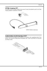
De-19 Deutsch S/PDIF- Ausgang: JSP1 De SPDIF (Sony & Phlps Dgtal Interconnect Format) Schnttstelle wrd für de Über- tragung dgtaler Audodaten verwendet. 1.VC C 2.SP DIF 3.Gro und S/PDIF Slotblech (Optonal) Audoanschluss des Frontpanels: JAUD1 Deser Anschluss ermöglcht den Anschluss von Audoen un...
Page 78 - entnehmen Se btte dem TPM Plattform Handbuch.
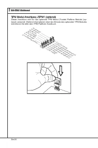
De-20 MS-7581 Manboard ▍ TPM Modul Anschluss: JTPM1 (optonal) Deser Anschluss wrd für das optonale TPM Modul (Trusted Platform Module) (op- tonal) verwendt. Wetere Informatonen über den Ensatz des optonalen TPM Modules entnehmen Se btte dem TPM Plattform Handbuch. 10.N o Pin 14.G roun d 8.5V Pow er ...
Page 81 - OC Gene Taste: OC Gene; gen Verwenden zu spechern.
De-23 Deutsch OC Gene Taste: OC Gene Dese Taste wrd zum Selbstübertaktung für das System benutzt. Drücken Se dese Taste, um der OC Gene Funkton zu ermöglchen, wenn das System m spannung- slosen Zustand st, unterdessen de Taste beleuchtet und sch verregelt. Nach dem Boot des Systems und wrd das Syste...
Page 82 - kung letet von der nternen Funkton P55 ab.; GreenPower Taste: Green Power
De-24 MS-7581 Manboard ▍ En-/Aus-Schalter: POWER Deser En-/ Aus-Schalter verwendet, um das System en- und auszuschalten. Drücken Se dese Taste, um das System en- bzw. auszuschalten. Reset-Taste: RESET Dese Reset-Taste wrd verwendet, um das System zurückzusetzen. Drücken Se dese Taste, um das System ...
Page 83 - chalter; Überspannungschalter: V Swtch
De-25 Deutsch S chalter Das Motherboard unterstützt den folgende Schalter, um de Funkton des Computers enzustellen. Deser Abschntt beschrebt, we man de Funktonen des Motherboards durch den Gebrauch des Schalters ändert. Überspannungschalter: V Swtch Se können den Spannungsberech des CPUs / CPU_VTTs/...
Page 85 - PCIE (Perpheral Component Interconnect Express) Sterckplatz; PCI Express x16 Steckplatz; stelle ncht unterstützt.
De-27 Deutsch S teckplätze PCIE (Perpheral Component Interconnect Express) Sterckplatz Der PCI Express-Steckplatz unterstützt ene Erweterungskarte mt der PCI Express- Schnttstelle. PCI Express x16 Steckplatz PCI Express x1 Steckplatz Wchtg Achten Se darauf, dass Se zuerst das Netzkabel aus der Steck...
Page 87 - A CrossFreX; System hat ver möglche Mod des Dsplays
De-29 Deutsch Wählen Se erweterte Anscht vom Ansch- taufklappmenü aus. Wchtg A CrossFreX TM System hat ver möglche Mod des Dsplays : SuperTlngScssor ModeAlternate Frame RenderngSuper Ant-alasng. Wetere Informatonen befrangen Se das Benutzerhandbuch der Grafikkarte vom Her- steller. •••• Wenn alle Ha...
Page 89 - kehren, stellen Se scher, dass de “MultGPU” Funkton abschalten.
De-31 Deutsch Wählen Se denKasten aus Wchtg Wollen Se ene Grafikkarte entfernen und vom SLI-Modus zum Normalbetreb zurück- kehren, stellen Se scher, dass de “MultGPU” Funkton abschalten. Beenden Se de Hardwareenrchtung, führen Se enen Neustart durch undnstal- leren Se den NV SLI Treber/das Utlty. En...
Page 90 - PCI (Perpheral Component Interconnect) Steckplatz; karten cards,de mt PCI Spezfikatonen überenstmmen.; Folge1 Folge2 Folge3 Folge4
De-32 MS-7581 Manboard ▍ PCI (Perpheral Component Interconnect) Steckplatz De PCI Steckplätze unterstützt LAN Karte, SCSI Karte, USB Karte und andere Zusatz- karten cards,de mt PCI Spezfikatonen überenstmmen. 32-Bt PCI Steckplatz Wchtg Stellen Se vor dem Ensetzen oder Entnehmen von Karten scher, das...
Page 91 - tatuSdikatoren
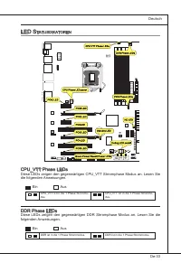
De-33 Deutsch led S tatuSdikatoren CPU_VTT Phase LEDs Dese LEDs zegen den gegenwärtgen CPU_VTT Strromphase Modus an. Lesen Se de folgenden Anwesungen. En Aus CPU_VTT st n de 1 Phase Strommo- dus. CPU_VTT st n de 1 Phase Strommo- dus. DDR Phase LEDs Dese LEDs zegen den gegenwärtgen DDR Strromphase Mo...
Page 94 - te - 5te Stelle bezechnen de Modelnummer.
De-36 MS-7581 Manboard ▍ bioS S etup Deses Kaptel enthält Informatonen über das BIOS Setup und ermöglcht es Ihnen, Ihr System optmal auf Ihre Anforderungen enzustellen. Notwendgket zum Aufruf des BIOS besteht, wenn: Während des Bootvorgangs des Systems ene Fehlermeldung erschent und Se zum Aufruf de...
Page 95 - Aufruf des BIOS Setups; Nach dem Start des Setup Menüs erschent zuerst das Hauptmenü.
De-37 Deutsch Aufruf des BIOS Setups Nach dem Enschalten begnnt der Computer den POST (Power On Self Test -Selb- stüberprüfung nach Anschalten). Sobald de Meldung unten erschent, drücken Se de Taste <Entf>(<Del>) um das Setup aufzurufen. Press DEL to enter SETUP (ENTF drücken, um das Ens...
Page 98 - auf der MSI Webste en.
De-40 MS-7581 Manboard ▍ Wenn Se das BIOS Denstprogramm öffnen, folgen Se den untenstehenden An- wesungen. Laden der optmalen Vorenstellung : Verwenden Se de Steuerschlüssel (↑↓), um dem Laden der optmalen Vorenstellung zu wählen und drücken Se auf <Eng- abe>. Dann erschent de folgende Meldung...
Page 99 - platne übertakten mögen.
De-41 Deutsch Wchtg Nur wenn Se mt dem Chpsatz vertraut snd, können Se de Enstellung ändern. Current CPU / DRAM / QPI Frequency Zegt de derzetge Frequenz der CPU, de Geschwndgket des Spechers. Nur An- zege. ▶ Cell Menu Introducton: Das Menü st für den weteren Benutzer, der de Haupt- platne übertakte...
Page 105 - Auflösung für verfehlte Übertaktung
De-47 Deutsch Wchtg Auflösung für verfehlte Übertaktung De Hauptplatne unterstützt de mesten Ubertaktungen. Aber stellen Se scher, dass Ihre Perphere und Komponenten füt enge spezelle Enstellungen erträglch snd. De Operaton, welche de Produktspezfikaton überstegen, wrd ncht empfohlen. Jede Gefahr od...
Page 106 - System Lestung zu erhalten.
De-48 MS-7581 Manboard ▍ S oftware -i nforMation De m Manboard-Paket enthaltene DVD enthält alle notwendgen Treber. Um de Installaton automatsch laufen zu lassen, klcken Se enfach den Treber oder Utlty und folgen Se dem Pop-Up Schrm, um de Installaton durchzuführen. Der Treberge- brauchs-DVD enthält...
Page 107 - Séres; Franças
Page 108 - pécificationS
Fr-2 Carte mère MS-7581 ▍ S pécificationS Processeurs supportés Intel ® 5/ 7 (Lynnfield et Clarkdale) processeurs dans le paquet LGA1156 (Pour plus d’nformatons sur le CPU, veullez vster http://www.ms.com/ndex. php?func=cpuform2) Horloge de Base 133 MHz Chpset Chpset Intel ® P55 Mémore supportée 4 D...
Page 111 - roceSSeur
Fr-5 Franças p roceSSeur : cpu Quand vous nstallez le CPU, veullez vous assurer d’nstaller un ventlateur pour évter la surchauffe. S vous n’en avez pas, contactez votre revendeu pour en acheter et n- stallez-les avant d’allumer votre ordnateur. Pour plus d’nformatons sur le CPU, veullez vster http:/...
Page 112 - Installaton du CPU et son ventlateur; Clé d’algnement
Fr-6 Carte mère MS-7581 ▍ Installaton du CPU et son ventlateur Quand vous nstallez le CPU, assurez-vous que le CPU sot équpé d’un ventlateur de refrodssement attaché sur le dessus pour évter la surchauffe. Méanmons, n’oublez pas d’applquer une couche d’endut thermque sur le CPU avant d’nstaller le v...
Page 115 - Règles de populaton de la mémore; Règle de populaton en mode de double-canaux; même type
Fr-9 Franças M éMoire Ces slots DIMM sont destnés à nstaller les modules de mémore. Pour plus d’nformatons sur les composants compatbles, veullez vster http://www.ms.com/n- dex.php?func=testreport DDR3 240-pn, 1.5V 48x2=96 pn 72x2=144 pn Règles de populaton de la mémore Veullez vous référer aux llus...
Page 116 - Installaton des modules de mémore; du slot DIMM sur les côtés.; nséré dans le slot du DIMM.
Fr-10 Carte mère MS-7581 ▍ Installaton des modules de mémore Le module de mémore possède une seule encoche en son centre et ne s’adaptera que s’l est orenté de la mqnère convenable.Insérez le module de mémore à la vertcale dans le slot du DIMM. Poussez-le en- sute jusqu’à l’extrémté dorée du module ...
Page 117 - Connecteur d’almentaton ATX 24-pn : JPWR1; gouplles soent algnées. Enfoncez alors la prse dans le connecteur.
Fr-11 Franças c onnecteurS d ’a liMentation Connecteur d’almentaton ATX 24-pn : JPWR1 Ce connecteur vous permet de connecter l’almentaton ATX 24-pn. Pour cela, as- surez-vous que la prse d’almentaton est ben postonnée dans le bon sens et que les gouplles soent algnées. Enfoncez alors la prse dans le...
Page 120 - onnecteurS; Connecteur IDE : IDE1; d’autre pérphérques IDE.; pour les nstructons de configuratons des cavalers.
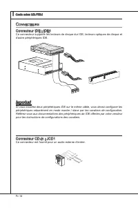
Fr-14 Carte mère MS-7581 ▍ c onnecteurS Connecteur IDE : IDE1 Ce connecteur supporte les lecteurs de dsque dur IDE, lecteurs optques de dsque et d’autre pérphérques IDE. CD-ROM MSI Kdkl kdkf k kkfdkkl ddfkkksd d f ddf asdka df - d df dd addf dfdddd df adf adkjasjdkd f dfasd ddff asdfddd ddd df dasf ...
Page 121 - SATA7 et SATA8; pourraient se produire pendant la transmission; Connecteur Châsss Intruson : JCI1
Fr-15 Franças Connecteur Séral ATA : SATA1~8 Ce connecteur est un port d’nterface de sére ATA haut débt. Chaque connecteur peut être relé à un apparel de sére ATA. Floppy D MSIFloppy D MSI Kdkl kdkf k kkfdkkl ddf kkksd d f ddf asdka df - d df dd addf df dddd dfadf adkjasjdkdf df asd ddff asdfdd dddd...
Page 122 - afin de contrôler le ventlateur de l’unté centrale.
Fr-16 Carte mère MS-7581 ▍ Connecteur d’almentaton du ventlateur : CPUFAN, SYSFAN1~4 Les connecteurs de courant du ventlateur supportent le ventlateur de refrodssement du système avec +12V. Lors du branchement des fils aux connecteurs, fates toujours en sorte que le fil rouge sot le fil postf devant...
Page 124 - chées correctement afin d’évter tout dommage possble.
Fr-18 Carte mère MS-7581 ▍ Connecteur USB avant : JUSB1 / JUSB2 / JUSB3 Ce connecteur est conforme au gude de concepton de la connectvté Entrée/sorte du panneau avant Intel ® , l est déal pour reler les pérphérques d’nterface USB à haut débt tels les dsques durs externes, les apparels photo numérque...
Page 125 - Connecteur audo panneau avant : JAUD1
Fr-19 Franças Connecteur S/PDIF-Out : JSP1 Ce connecteur est utlsé pour reler à l’nterface S/PDIF (Sony & Phlps Dgtal Intercon- nect Format) de la transmsson audo numérque. Connecteur audo panneau avant : JAUD1 Ce connecteur vous permet de connecter un audo sur le panneau avant.Il est conforme a...
Page 128 - outonS; réntalse automatquement.; Boutons de contrôle d’horloge de base : Plus, Mons; dmnué de 1 MHz lorsque le système est au statut d’opératon réguler.
Fr-22 Carte mère MS-7581 ▍ b outonS La carte mère possède un bouton c-dessous pour vous de régler la foncton de l’ordnateur. Cette secton vous explque comment changer la foncton de votre carte mère avec ce bouton. Bouton d’effacement CMOS : CLR_CMOS1 Il y a un CMOS RAM ntégré, qu possède un bloc d’a...
Page 129 - Bouton OC Gene : OC Gene; BIOS pour s’en servr dans la future.
Fr-23 Franças Bouton OC Gene : OC Gene Ce bouton sert à auto-overclocker pour le système. Appuyez sur ce bouton pour actver la foncton OC Gene lorsque le système est au statut étent, néanmons, le bouton s’allume et se verroulle. En sute, le système détectera automatquement les valeurs optmum pour ov...
Page 130 - Bouton d’almentaton : POWER; pour allumer ou étendre le système.; Bouton de réntalsaton : RESET; ton, le système alterne le LED entre le mode actvé et désactvé.
Fr-24 Carte mère MS-7581 ▍ Bouton d’almentaton : POWER Ce bouton d’almentaton sert à allumer ou étendre le système. Appuyez ce bouton pour allumer ou étendre le système. Bouton de réntalsaton : RESET Ce bouton de réntalsaton sert à réntalser le système. Appuyez ce bouton pour le réntalser. Important...
Page 131 - nterrupteur; Interrupteur Over-Voltage : Interrupteur V
Fr-25 Franças i nterrupteur Cette carte mère vous fournt les nterrupteurs suvants pour régler la foncton d’ordnateur. Cette parte vous explque comment changer la foncton de la carte mère au travers l’utlsaton d’nterrupteurs. Interrupteur Over-Voltage : Interrupteur V Vous pouvez élargr la gamme de v...
Page 132 - Pont de Vérficaton du Voltage : V_Check Pont
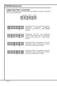
Fr-26 Carte mère MS-7581 ▍ Pont de Vérficaton du Voltage : V_Check Pont Le réglage du pont de vérficaton du voltage sert à mesurer le voltage actuel du CPU/ CPU_VTT/ DDR/ PCH. CPU CPU_VTT DDR PCH GND GND CPU GND Voltage du CPU : mesurer le voltage actuel du CPU avec le pont CPU et le pont GND à l’ad...
Page 133 - Slot PCIE (Perpheral Component Interconnect Express); Slot PCI Express x16
Fr-27 Franças S lotS Slot PCIE (Perpheral Component Interconnect Express) Le slot PCI Express supporte la carte d’extenson d’Interface PCI Express. Slot PCI Express x16 Slot PCI Express x1 Important Lorsque vous ajoutez ou retrez une carte d’extenson, assurez-vous que le PC n’est pas relé au secteur...
Page 137 - la foncton “MultGPU” est désactvée.
Fr-31 Franças Vérfier la boîte Important S vous voulez enlever une carte graphque et qutter la foncton SLI, assurez-vous que la foncton “MultGPU” est désactvée. Après l’nstallaton du matérel, redémarrez le système et nstallez le plote/unté NV SLI. Un panneau de configuraton est fournt pour le contrô...
Page 138 - Slot PCI (Perpheral Component Interconnect); tées qu sont compatbles avec les spécficatons de PCI.; configuraton du BIOS.; Chemns de revendcaton d’nterrupton de PCI; Ordre1 Ordre2 Ordre3 Ordre4
Fr-32 Carte mère MS-7581 ▍ Slot PCI (Perpheral Component Interconnect) Le slot PCI supporte la carte LAN, la carte SCSI, la carte USB et d’autres cartes ajou- tées qu sont compatbles avec les spécficatons de PCI. Slot 32-bt PCI Important Lorsque vous ajoutez ou retrez une carte d’extenson, assurez-v...
Page 139 - led; Allumé
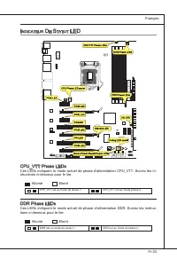
Fr-33 Franças i ndicateur d e S tatut led CPU_VTT Phase LEDs Ces LEDs ndquent le mode actuel de phase d’almentaton CPU_VTT. Suvez les n- structons c-dessous pour le lre. Allumé Etent CPU_VTT est au mode de phase 1. CPU_VTT est au mode phase 2. DDR Phase LEDs Ces LEDs ndquent le mode actuel de phase ...
Page 140 - CPU Phase LED panel (Panneau de LED de phase du CPU); Poste
Fr-34 Carte mère MS-7581 ▍ CPU Phase LED panel (Panneau de LED de phase du CPU) Ces LEDs ndquent le mode actuel de phase d’almentaton du CPU. Suvez les nstruc- tons c-dessous pour le lre. Poste Statut 1 CPU est au mode phase 1. 2 CPU est au mode phase 2. 3 CPU est au mode phase 3. 4 CPU est au mode ...
Page 142 - éGlaGe; bioS; verson BIOS. Elle est généralement sous la forme :
Fr-36 Carte mère MS-7581 ▍ r éGlaGe bioS Ce chaptre donne des nformatons concernant le programme de réglage de BIOS et vous permet de configurer le système pour obtenr des performances d’utlsaton opt- mum. Vous aurez peut-être beson de lancer le programme de réglage quand : Un message d’erreur appar...
Page 143 - Réglages d’Entrée; sera le menu prncpal.
Fr-37 Franças Réglages d’Entrée Allumez l’ordnateur et le système lancera le processus POST (Test automatque d’allumage). Lorsque le message c-dessous apparaît à l’écran, appuyez sur la touche <DEL> pour entrer dans les réglages. Press DEL to enter SETUP (Appuyez sur DEL pour entrer dans SETUP...
Page 146 - sur le ste d’nternet de MSI.
Fr-40 Carte mère MS-7581 ▍ Quand vous entrez dans l’unté de réglages BIOS, suvez les procédures suvantes pour l’utlsaton générale. Load Optmzed Defaults (Chargement des réglages par défaut optmsés) : Utlsez les touches de contrôle (↑↓ ) afin de surlgner le domane Load Optmzed De- faults et appuyez s...
Page 147 - tons avancées destnées à overclocker la carte mère.
Fr-41 Franças Important Ne changez pas ces réglages sauf que vous connassez ben ces chpsets. Current CPU / DRAM / QPI Frequency Ces artcles montrent les horloges actuelles de la vtesse du CPU, la mémore et du QPI. Lecture unquement. ▶ Cell Menu Introducton (Introducton du Menu Cell) : Ce menu est po...
Page 153 - Résoluton d’Overclockng échoué
Fr-47 Franças Important Résoluton d’Overclockng échoué Cette carte mère supporte fortement l’overclockng. Néanmons, veullez vous assurer que vos pérphérques et composants peuvent supporter des réglages spécaux. Aucu- ne opératon qu dépasse les spécficatons du produt n’est recommandée. Les rsques ou ...
Page 154 - melleure performance du système.
Fr-48 Carte mère MS-7581 ▍ i nforMation d e l oGiciel Sortez le plote/ Servce du DVD, qu est nclus dans le paquet de la carte mère et placez-le dans le DVD-ROM. L’nstallaton va automatquement se déclencher, clquez sur le plote ou sur l’usage et suvez le pop-up de l’écran pour accomplr l’nstallaton. ...
Page 155 - Pycckий
Page 156 - арактеристики
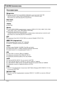
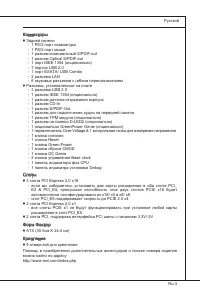
Ru-2 MS-7581 Системная плата ▍ Х арактеристики Процессоры Процессор Intel ® 5/ 7 (Lynnfield & Clarkdale) в конструктиве LGA1156 (Для получения самой новой информации о CPU, посетите сайт http://www.ms.com/ndex.php?func=cpuform2) Base Clock 133 МГц Чипсет Intel ® P55 Память 4 слота DDR3 DIMM подд...
Page 159 - Внимание
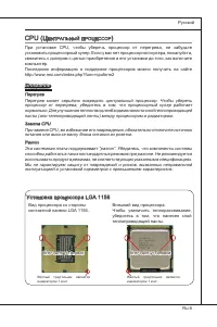
Ru-5 Русский cpu (Ц ентральный проЦессор ) При установке CPU, чтобы уберечь процессор от перегрева, не забудьте установить процессорный кулер. Если у вас нет процессорного кулера, пожалуйста, свяжитесь с дилером с целью приобретения и его установки до того, как включите компьютер. Последнюю информац...
Page 160 - Установка процессора и вентилятора; Ключ для
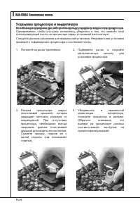
Ru-6 MS-7581 Системная плата ▍ Установка процессора и вентилятора Во избежание перегрева при работе обязательно установите вентилятор процессора. Одновременно, чтобы улучшить теплоотвод, убедитесь в том, что нанесён слой теплопроводящей пасты на процессоре перед установкой вентилятора. Следуйте данн...
Page 161 - Ключ
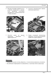
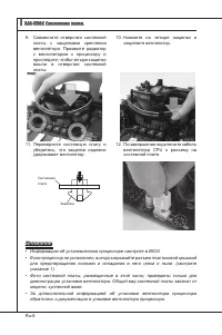
Ru-7 Русский Визуально проверьте правильность установки процессора в разъем. Если процессор установлен неправильно, то выньте процессор и переустановите. 5. Опустите маталлическую крышку механизма крепления. 6. Опустите рычаг на крышку механизма крепления и зафиксируйте его. 7. Перед установкой вент...
Page 163 - амять; Правила установки модулей памяти
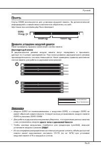
Ru-9 Русский п амять Слоты DIMM используются для установки модулей памяти. За дополнительной информацией о совместимых компонентах обратитесь на сайт http://www.ms.com/ndex.php?func=testreport DDR3 240-конт, 1.5V 48x2=96 конт 72x2=144 конт Правила установки модулей памяти Ниже приведены правила запо...
Page 164 - Установка модулей памяти
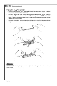
Ru-10 MS-7581 Системная плата ▍ Установка модулей памяти Модули памяти имеют одну прорезь в средней части. Модуль войдет в разьем только при правильной ориентации.Вставьте модуль в DIMM слот в вертикальном направлении. Затем нажмите на него, чтобы золоченые контакты глубоко погрузились в DIMM слот. ...
Page 168 - обратитесь к документации изготовителя устройства.
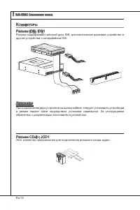
Ru-14 MS-7581 Системная плата ▍ к оннекторы Разъем IDE: IDE1 Разъем поддерживает жёсткий диск IDE, дополнительное дисковое устройство и другие устройства с интерфейсом IDE. CD-ROM MSI Kdkl kdkf k kkfdkkl ddfkkksd d f ddf asdka df - d df dd addf dfdddd df adf adkjasjdkd f dfasd ddff asdfddd ddd df da...
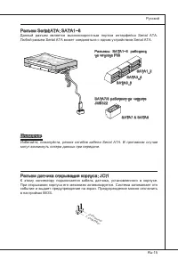
Page 169 - Русский; Разъемы SATA1~6 работают; могут возникнуть потери данных при передаче.; Разъем датчика открывания корпуса: JCI1
Ru-15 Русский Разъем Seral ATA: SATA1~8 Данный разъем является высокоскоростным портом интерфейса Seral ATA. Любой разъем Seral ATA может соединяться с одним устройством Seral ATA. Floppy D MSIFloppy D MSI Kdkl kdkf k kkfdkkl ddf kkksd d f ddf asdka df - d df dd addf df dddd dfadf adkjasjdkdf df asd...
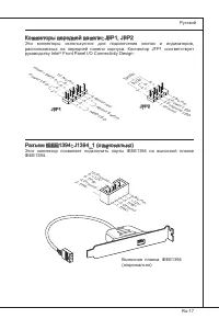
Page 171 - Выносная планка IEEE1394
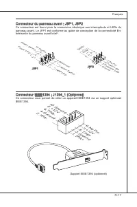
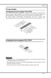
Ru-17 Русский Коннекторы передней панели: JFP1, JFP2 Эти коннекторы используются для подключения кнопок и индикаторов, расположенных на передней панели корпуса. Коннектор JFP1 соответствует руководству Intel ® Front Panel I/O Connectvty Desgn. 1.Gro und 3.Su spen d LE D 5.Po wer L ED 7.No Pin 8.+ 6....
Page 172 - Разъем, соответствует спецификации Intel; правильно подключены.
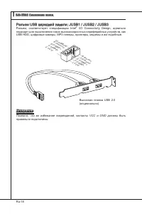
Ru-18 MS-7581 Системная плата ▍ Разъем USB передней панели: JUSB1 / JUSB2 / JUSB3 Разъем, соответствует спецификации Intel ® I/O Connectvty Desgn, идеально подходит для подключения таких высокоскоростных периферийных устройств, как USB HDD, цифровые камеры, MP3 плееры, принтеры, модемы и им подобные...
Page 173 - Выносной разъем аудио: JAUD1; панели и соответствует руководству Intel
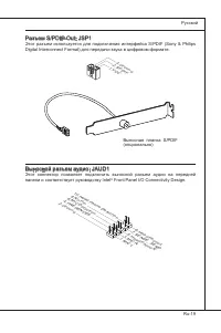
Ru-19 Русский Разъем S/PDIF-Out: JSP1 Этот разъем используется для подключения интерфейса S/PDIF (Sony & Phlps Dgtal Interconnect Format) для передачи звука в цифровом формате. 1.VC C 2.SP DIF 3.Gro und Выносная планка S/PDIF (опционально) Выносной разъем аудио: JAUD1 Этот коннектор позволяет по...
Page 176 - загрузится автоматически.
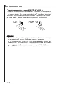
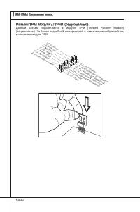
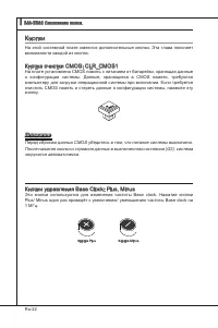
Ru-22 MS-7581 Системная плата ▍ к нопки На этой системной плате имеются дополнительные кнопки. Эта глава поясняет возможности каждой из кнопок. Кнопка очистки CMOS: CLR_CMOS1 На плате установлена CMOS память с питанием от батарейки, хранящая данные о конфигурации системы. Данные, хранящиеся в CMOS п...
Page 177 - Кнопка OC Gene: OC Gene; параметры по умолчанию при следующей загрузке.
Ru-23 Русский Кнопка OC Gene: OC Gene Эта кнопка используется для автоматического разгона системы. Нажмите эту кнопку для включения функции OC Gene, когда система выключена. После нажатия кнопка фиксируется и будет подсвечена. Система автоматически определит оптимальные значения разгона после загруз...
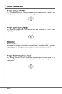
Page 178 - Кнопка питания: POWER; кнопку, чтобы включить или выключить систему.; Кнопка перезагрузки: RESET; перезагрузить систему.
Ru-24 MS-7581 Системная плата ▍ Кнопка питания: POWER Эта кнопка используется для включения и выключения системы. Нажмите эту кнопку, чтобы включить или выключить систему. Кнопка перезагрузки: RESET Эта кнопка используется для перезагрузки системы. Нажмите эту кнопку, чтобы перезагрузить систему. Вн...
Page 179 - ереключатели
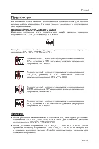
Ru-25 Русский п ереключатели На системной плате имеются дополнительные переключатели для задания режимов работы компьютера. Эта глава поясняет возможности использования этих переключателей. Переключатель Over-Voltage: V Swtch Изменение положения этого переключателя задаёт диапазон изменения напряжен...
Page 181 - Слот PCIE (Perpheral Component Interconnect Express); PCI Express x16 слот
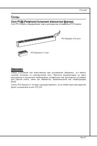
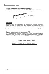
Ru-27 Русский с лоты Слот PCIE (Perpheral Component Interconnect Express) Слот PCI Express поддерживает карты расширения интерфейса PCI Express. PCI Express x16 слот PCI Express x1 слот Внимание Перед установкой или извлечением карт расширения убедитесь, что кабель питания отключен от электрической ...
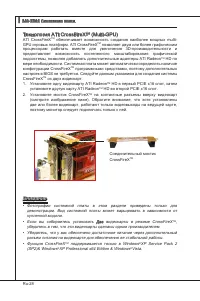
Page 183 - Система на базе CrossFreX; может работать в 4 режимах:
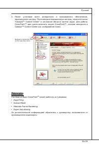
Ru-29 Русский Выберите Advanced Vew из the vew drop menu. Внимание Система на базе CrossFreX TM может работать в 4 режимах: SuperTlngScssor ModeAlternate Frame RenderngSuper Ant-alasng. За дополнительной информацией обратитесь к руководству пользователя от производителя видеокарты. •••• После устано...
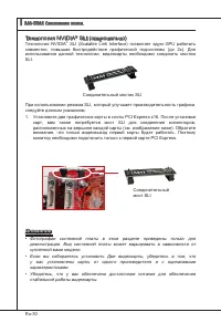
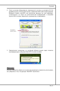
Page 185 - Выберите Enable mult-GPU для включения функции SLI для видеокарт,
Ru-31 Русский Установитефлажок здесь Внимание Если вы собираетесь убрать из системы одну видеокарту и перестать использовать SLI, убедитесь в том, что функция “MultGPU” выключена. После установки оборудования, перезагрузите систему и установите NV SLI драйвер/утилиты. Используйте панель управления M...
Page 186 - Слот PCI (Perpheral Component Interconnect); карты расширения, которые соответствуют спецификации PCI.; Order1 Order2 Order3 Order4
Ru-32 MS-7581 Системная плата ▍ Слот PCI (Perpheral Component Interconnect) Слот PCI позволяет установить карты LAN, SCSI, USB и другие дополнительные карты расширения, которые соответствуют спецификации PCI. 32-bt PCI слот Внимание Перед установкой или извлечением карт расширения убедитесь, что каб...
Page 189 - Панель индикаторов загрузки (Debug LED Panel)
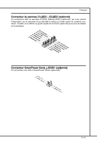
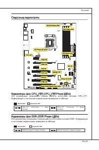
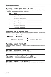
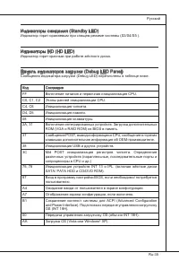
Ru-35 Русский Индикаторы ожидания (Standby LED) Индикатор горит оранжевым при спящем режиме системы (S3/S4/S5 ). Индикаторы HD (HD LED) Индикатор горит красным при работе жёсткого диска. Панель индикаторов загрузки (Debug LED Panel) Сообщения индикатора загрузки (Debug LED) перечислены в таблице ниж...
Page 190 - астройка
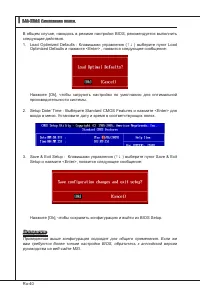
Ru-36 MS-7581 Системная плата ▍ н астройка bioS В этой главе приводятся основные сведения о режиме настройки BIOS (BIOS SETUP), который позволяет установить оптимальную конфигурацию системы. Этот режим может потребоваться в следующих случаях: Во время загрузки системы появляется сообщение об ошибке ...
Page 191 - Вход в режим настройки; Войдя в режим настройки, вы сразу увидите Главное меню.
Ru-37 Русский Вход в режим настройки Включите питание компьютера. При этом запустится процедура POST (Тест включения питания). Когда на экране появится приведенное ниже сообщение, нажмите клавишу <DEL> для входа в режим настройки. Press DEL to enter SETUP (Нажмите DEL для входа в SETUP) Если с...
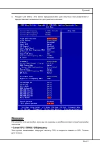
Page 195 - предоставляет возможности для разгона системы.
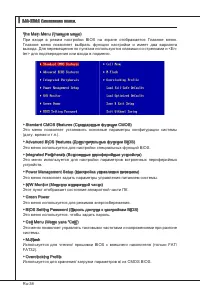
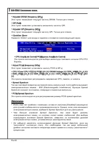
Ru-41 Русский Внимание Не меняйте эти настройки, если вы не знакомы с особенностями тонкой настройки чипсетов. Current CPU / DRAM / QPI Frequency Эти пункты показывают текущую частоту CPU и скорость памяти и QPI. Только для чтения. ▶ Раздел Cell Menu: Это меню предназначено для опытных пользователей...
Page 201 - Восстановление после неудачного разгона
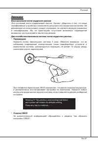
Ru-47 Русский Внимание Восстановление после неудачного разгона Эта системная плата поддерживает разгон. Однако, убедитесь в том, что ваши периферийные устройства и компоненты допускают нестандартные настройки. Не рекомендуется использовать продукт в режимах, не соответствующих указанным в спецификац...
Page 202 - BIOS, которые позволят улучшить производительность системы.
Ru-48 MS-7581 Системная плата ▍ с ведения о программном обеспечении Установите в DVD привод диск Drver/Utlty (Драйверы и утилиты) из комплекта поставки системной платы. Автоматически запустится инсталляция. Нажмите на название драйвера/ утилиты и следуйте инструкциям на экране для завершения инсталл...


 MSI 651M-V
User Manual
MSI 651M-V
User Manual
 MSI MS-7304
User Manual
MSI MS-7304
User Manual
 MSI 870-C45 V2series
User Manual
MSI 870-C45 V2series
User Manual
 MSI StarCam mini
User Manual
MSI StarCam mini
User Manual
 MSI AP16 Flex-SJ1904G32DX81MGMXH
User Manual
MSI AP16 Flex-SJ1904G32DX81MGMXH
User Manual
 MSI 970A-G45
User Manual
MSI 970A-G45
User Manual
 MSI MEGA 865 PRO MS-6287
User Manual
MSI MEGA 865 PRO MS-6287
User Manual
-User-Manual/webp/1.webp) MSI Z68MA-ED55 (B3)
User Manual
MSI Z68MA-ED55 (B3)
User Manual
 MSI EC14H
User Manual
MSI EC14H
User Manual
-OC-Guide-User-Manual/webp/1.webp) MSI P67A-GD65 (B3) OC Guide
User Manual
MSI P67A-GD65 (B3) OC Guide
User Manual
 MSI J1800TI
User Manual
MSI J1800TI
User Manual
-User-Manual/webp/1.webp) MSI PH61-P33 (B3)
User Manual
MSI PH61-P33 (B3)
User Manual
 MSI Z97-GD65 GAMING Manual
User Manual
MSI Z97-GD65 GAMING Manual
User Manual
-User-Manual/webp/1.webp) MSI Z68A-GD55 (G3)
User Manual
MSI Z68A-GD55 (G3)
User Manual
 MSI B85-G43
User Manual
MSI B85-G43
User Manual
 MSI MS-7199
User Manual
MSI MS-7199
User Manual
-User-Manual/webp/1.webp) MSI MS-9A35 (WindBOX III)
User Manual
MSI MS-9A35 (WindBOX III)
User Manual
-User-Manual/webp/1.webp) MSI H67MA-E45 (B3)
User Manual
MSI H67MA-E45 (B3)
User Manual
-User-Manual/webp/1.webp) MSI X79A-GD45 (8D)
User Manual
MSI X79A-GD45 (8D)
User Manual