Page 2 - Copyrght Notce
Preface MS-7640 Preface Preface MS-7640 Preface Copyrght Notce The materal n ths document s the ntellectual property of MICRO-STAR INTERNATIONAL. We take every care n the preparaton of ths document, but no guarantee s gven as to the correctness of ts contents. Our products are under contnual mprovem...
Page 3 - Safety Instructons
Preface MS-7640 Preface Preface MS-7640 Preface Safety Instructons Always read the safety nstructons carefully.Keep ths User’s Manual for future reference.Keep ths equpment away from humdty.Lay ths equpment on a relable flat surface before settng t up.The openngs on the enclosure are for ar convecto...
Page 4 - FCC-B Rado Frequency Interference Statement
v Preface MS-7640 Preface Preface MS-7640 Preface FCC-B Rado Frequency Interference Statement Ths equpment has been tested and found to comply wth the lmts for a Class B dg- tal devce, pursuant to Part 15 of the FCC Rules. These lmts are desgned to provde reasonable protecton aganst harmful nter- fe...
Page 5 - Preface; Preface; Preface; WEEE (Waste Electrcal and Electronc Equpment) Statement; ENGLISH; schlesslch an ener lokalen Altgerätesammelstelle n Ihrer Nähe.; FRANÇAIS; эти изделия в специализированные пункты приема.
Preface MS-7640 Preface v Preface MS-7640 Preface WEEE (Waste Electrcal and Electronc Equpment) Statement ENGLISH To protect the global envronment and as an envronmentalst, MSI must re- mnd you that...Under the European Unon (“EU”) Drectve on Waste Electrcal and Elec- tronc Equpment, Drectve 2002/96...
Page 6 - ESPAÑOL; empresa autorzada para la recogda de estos resduos.; NEDERLANDS; lokale nzamelngspunten.; SRPSKI; vode možete vratt na lokalnm mestma za prkupljanje.; POLSKI
v Preface MS-7640 Preface Preface MS-7640 Preface ESPAÑOL MSI como empresa comprometda con la proteccón del medo ambente, recomenda:Bajo la drectva 2002/96/EC de la Unón Europea en matera de desechos y/o equ- pos electróncos, con fecha de rgor desde el 13 de agosto de 2005, los productos clasficados...
Page 7 - TÜRKÇE; noktalarına bırakablrsnz.; ČESKY; cclo d vta. È possble portare prodott nel pù vcno punto d raccolta
Preface MS-7640 Preface v Preface MS-7640 Preface TÜRKÇE Çevrec özellğyle blnen MSI dünyada çevrey korumak çn hatırlatır:Avrupa Brlğ (AB) Kararnames Elektrk ve Elektronk Malzeme Atığı, 2002/96/EC Kararnames altında 13 Ağustos 2005 tarhnden tbaren geçerl olmak üzere, elektrkl ve elektronk malzemeler ...
Page 11 - Englsh; Europe verson
Page 12 - Manboard Specficatons
En-2 MS-7640 Manboard Manboard Specficatons Processor Support AMD ® Phenom TM II X6/ X4/ X3/ X2, Athlon TM II X4/ X3/ X2 and Sempron TM processor n the AM3+ package. (For the latest nformaton about CPU, please vst http://www.ms.com/servce/cpu- support/) HyperTransport HyperTransport™ 3.0, supports u...
Page 14 - Quck Components Gude
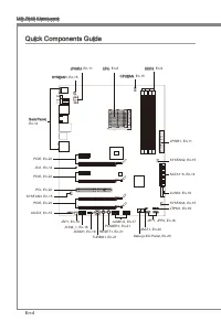
En-4 MS-7640 Manboard S O C K E T A M 3 JPWR2, En-11 Quck Components Gude Back Panel, En-12 CPU, En-6 CPUFAN, En-15 DDR3, En-9 SYSFAN1, En-15 JPWR1, En-11 SYSFAN2, En-15 SATA1~6, En-14 JUSB3, En-18 SYSFAN4, En-15JTPM1, En-19 JFP1, JFP2, En-16 JBAT1, En-20 Debug LED Panel, En-25 JUSB1/2, En-17 POWER1...
Page 15 - Screw Holes; Important
En-5 Englsh S O C K E T A M 3 Screw Holes When you nstall the manboard, you have to place the manboard nto the chasss n the correct drecton. The locatons of screws holes on the manboard are shown as below. Refer above pcture to nstall standoffs n the approprate locatons on chasss and then screw thro...
Page 16 - Overheatng; Introducton to AM3+ CPU
En-6 MS-7640 Manboard CPU (Central Processng Unt) When you are nstallng the CPU, make sure to nstall the cooler to prevent overheatng. If you do not have the CPU cooler, consult your dealer before turnng on the computer. For the latest nformaton about CPU, please vst http://www.ms.com/servce/cpu-sup...
Page 17 - CPU & Cooler Installaton
En-7 Englsh CPU & Cooler Installaton When you are nstallng the CPU, make sure the CPU has a cooler attached on the top to prevent overheatng. Meanwhle, do not forget to apply some thermal paste on CPU before nstallng the heat snk/cooler fan for better heat dsperson. Follow the steps below to nst...
Page 19 - Memory; compatble components, please vst
En-9 Englsh Memory These DIMM slots are used for nstallng memory modules. For more nformaton on compatble components, please vst http://www.ms.com/servce/test-report/ DDR3 240-pn, 1.5V 48x2=96 pn 72x2=144 pn Dual-Channel mode Populaton Rule In Dual-Channel mode, the memory modules can transmt and re...
Page 20 - Installng Memory Modules
En-10 MS-7640 Manboard Installng Memory Modules The memory module has only one notch on the center and wll only fit n the rght orentaton.Insert the memory module vertcally nto the DIMM slot. Then push t n untl the golden finger on the memory module s deeply nserted n the DIMM slot. The plastc clp at...
Page 21 - Power Supply; ATX power supply, please plug your power supply along wth pn 1 & pn 13.; sure stable operaton of the manboard.
En-11 Englsh Power Supply ATX 24-pn Power Connector: JPWR1 Ths connector allows you to connect an ATX 24-pn power supply. To connect the ATX 24-pn power supply, make sure the plug of the power supply s nserted n the proper orentaton and the pns are algned. Then push down the power supply firmly nto ...
Page 22 - Back Panel; mouse/keyboard DIN connector s for a PS/2; audo transmsson to external speakers through a coaxal cable.
En-12 MS-7640 Manboard Back Panel Mouse/Keyboard The standard PS/2 ® mouse/keyboard DIN connector s for a PS/2 ® mouse/keyboard. Clear CMOS Button There s a CMOS RAM on board that has a power supply from external battery to keep the system configuraton data. Wth the CMOS RAM, the system can automatc...
Page 23 - LAN
En-13 Englsh USB 3.0 Port USB 3.0 port s backward-compatble wth USB 2.0 devces. Supports data transfer rate up to 5 Gbt/s (SuperSpeed). Important If you want to use a USB 3.0 devce, you must use the USB 3.0 cable to connect to the USB 3.0 port. eSATA/ USB 2.0 Combo Port The eSATA/USB 2.0 combo port ...
Page 24 - Connectors; to one Seral ATA devce.; occur durng transmsson.; Chasss Intruson Connector: JCI1; BIOS utlty and clear the record.
En-14 MS-7640 Manboard Connectors Seral ATA Connector: SATA1~6 Ths connector s a hgh-speed Seral ATA nterface port. Each connector can connect to one Seral ATA devce. * The MB layout n ths figure s for reference only. SATA5_6 SATA3_4 SATA1_2 SATA1~6 (6Gb/s) supported by SB950 Important Please do not...
Page 25 - CPUFAN
En-15 Englsh Fan Power Connectors: CPUFAN, SYSFAN1~4 The fan power connectors support system coolng fan wth +12V. When connectng the wre to the connectors, always note that the red wre s the postve and should be con- nected to the +12V; the black wre s Ground and should be connected to GND. If the m...
Page 26 - The JFP1 s complant wth Intel; nterface for dgtal audo transmsson.
En-16 MS-7640 Manboard Front Panel Connectors: JFP1, JFP2 These connectors are for electrcal connecton to the front panel swtches and LEDs. The JFP1 s complant wth Intel ® Front Panel I/O Connectvty Desgn Gude. 1.Gro und 3.Su spen d LE D 5.Po wer L ED 7.No Pin 8.+ 6.- 4.+ 2.- Buzz er Spea ker 1.+ 3....
Page 28 - Front USB Connector: JUSB3
En-18 MS-7640 Manboard Front USB Connector: JUSB3 USB 3.0 port s backward-compatble wth USB 2.0 devces. Supports data transfer rate up to 5 Gbt/s (SuperSpeed). 11 5 V 5.US B3_T X3_C _DN 4.Gro und 3.US B3_R X3_D P 2.US B3_R X3_D N 1.FU SB_V CC2 10.N C 9.SB D0+ 8.SB D0- 7.Gro und 6.US B3_T X3_C _DP 20...
Page 29 - TPM Module connector: JTPM1; TPM module s optonal; Seral Port Connector: JCOM1; bytes FIFOs. You can attach a seral devce.
En-19 Englsh TPM Module connector: JTPM1 Ths connector connects to a TPM (Trusted Platform Module) module (optonal). Please refer to the TPM securty platform manual for more detals and usages. * The MB layout n ths figure s for reference only. 11 5 V 10.N o Pin 14.G roun d 8.5V Pow er 12.G roun d 6....
Page 30 - Jumpers; Clear CMOS Jumper: JBAT1; set the jumper to clear data.
En-20 MS-7640 Manboard Jumpers Clear CMOS Jumper: JBAT1 There s a CMOS RAM onboard that has a power supply from an external battery to keep the data of system configuraton. Wth the CMOS RAM, the system can automat- cally boot OS every tme t s turned on. If you want to clear the system configuraton, ...
Page 31 - OC Gene Button: TURBO1; and the system wll restore the default for next boot.; Buttons
En-21 Englsh Ths secton wll explan how to change your motherboard’s functon through the use of followng buttons. OC Gene Button: TURBO1 Ths button s used to auto-overclock for the system. Press ths button to enable the OC Gene functon when the system s n power off state, meanwhle, the button wll lgh...
Page 32 - Slots; PCIE (Perpheral Component Interconnect Express) Slot
En-22 MS-7640 Manboard Slots PCIE (Perpheral Component Interconnect Express) Slot The PCIE slot supports the PCIE nterface expanson card. PCIE x16 Slot PCIE x1 Slot PCI (Perpheral Component Interconnect) Slot The PCI slot supports LAN card, SCSI card, USB card, and other add-on cards that comply wth...
Page 33 - LED Status Indcators; HDD LED
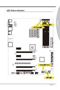
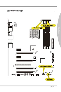
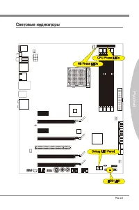
En-23 Englsh S O C K E T A M 3 LED Status Indcators HDD LED CPU Phase LEDs NB Phase LEDs Debug LED Panel
Page 35 - Debug LED Panel
En-25 Englsh Debug LED Panel Please refer to the table below to get more nformaton about the Debug LED mes- sage. Post Status D1 Perform keyboard controller BAT test. Check f wakng up from power man- agement suspend state. Save power-on CPUID value n scratch CMOS. 03 Dsable NMI, Party, vdeo for EGA,...
Page 36 - BIOS Setup
En-26 MS-7640 Manboard BIOS Setup Ths chapter provdes basc nformaton on the BIOS Setup program and allows you to configure the system for optmum use. You may need to run the Setup program when: An error message appears on the screen durng the system bootng up, and requests you to run BIOS SETUP. You...
Page 37 - Control
En-27 Englsh Control Keyboard Mouse Descrpton <↑><↓> Move the cursor Select Item <←><→> Select Screen <Enter> Clck/ Double- clck the left button Select Icon/ Feld <Esc> Clck the rght button Jumps to the Ext menu or returns to the prevous from a submenu <+> I...
Page 38 - The Man Menu
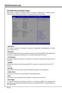
En-28 MS-7640 Manboard The Man Menu Once you enter BIOS CMOS Setup Utlty, the Man Menu wll appear on the screen. The Man Menu allows you to select from the setup functons. Man Menu Use ths menu for basc system configuratons, such as tme, date etc. Advanced Use ths menu to setup the tems of the BIOS ...
Page 43 - Software Informaton; Servce base menu : Through ths menu to lnk the MSI offically webste.
En-33 Englsh Software Informaton Take out the Drver/Utlty DVD that s ncluded n the manboard package, and place t nto the DVD-ROM drve. The nstallaton wll auto-run, smply clck the drver or utlty and follow the pop-up screen to complete the nstallaton. The Drver/Utlty DVD contans the: Drver menu : It ...
Page 45 - Deutsch; Europa Verson
Page 46 - Spezfikatonen
De-2 MS-7640 Manboard Spezfikatonen Prozessoren AMD ® Phenom TM II X6/ X4/ X3/ X2, Athlon TM II X4/ X3/ X2 und Sempron TM Prozesso- ren für Sockel AM3+. (Wetere CPU Informatonen finden Se unter http://www.ms.com/servce/cpu- support/) HyperTransport HyperTransport™ 3.0, unterstützt bs zu 5,2 GT/s Chp...
Page 47 - Anschlüsse
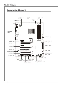
De-3 Deutsch Anschlüsse Hntere En-/ und Ausgänge 1 PS/2 Tastaturanschluss 1 PS/2 Mausanschluss 1 CMOS leeren-Taste 1 koaxaler S/PDIF-Ausgang 1 optscher S/PDIF-Ausgang 4 USB 2.0 Anschlüsse 2 USB 3.0 Anschlüsse 2 eSATA/ USB 2.0 Combo Anschlüsse 1 LAN Anschluss 1 IEEE 1394 Anschluss 6 Audobuchsen On-Bo...
Page 49 - board snd we nachfolgend gezegt.; Wchtg; Schraubenlöcher
De-5 Deutsch S O C K E T A M 3 Schraubenlöcher Wenn Se das Manboard zu nstalleren, müssen Se das Manboard n das Chasss n der korrekten Rchtung setzen. De Standorte von Schraubenlöchern auf dem Man- board snd we nachfolgend gezegt. Verwesen Se das obge Bld, um Abstandshalter n den entsprechenden Orte...
Page 50 - Überhtzung; De Obsersete der AM3+ CPU; um ene Abletung der Htze zu erzelen.
De-6 MS-7640 Manboard CPU (Prozessor) Wenn Se de CPU enbauen, stellen Se btte scher, dass Se auf der CPU enen Kühler anbrngen, um Überhtzung zu vermeden. Verfügen Se über kenen Kühler, setzen Se sch btte mt Ihrem Händler n Verbndung, um enen solchen zu erwerben und zu nstalleren. Um de neuesten Info...
Page 53 - tonen über kompatble Bautele finden Se unter
De-9 Deutsch Specher Dese DIMM-Steckplätze nehmen Arbetsspechermodule auf. De neusten Informa- tonen über kompatble Bautele finden Se unter http://www.ms.com/servce/test-re- port/ DDR3 240-polg, 1,5V 48x2=96 Pole 72x2=144 Pole Populatonsregeln für Dual-Kanal-Specher Im Dual-Kanal-Modus können Arbets...
Page 54 - Vorgehenswese bem Enbau von Specher Modulen
De-10 MS-7640 Manboard Vorgehenswese bem Enbau von Specher Modulen De Spechermodulen haben nur ene Kerbe n der Mtte des Moduls. Se passen nur n ener Rchtung n den Sockel.Stecken Se das Arbetsspechermodul senkrecht n den DIMM-Steckplatz en. Drücken Se anschleßnd das Arbetsspechermodul nach unten, bs ...
Page 55 - Verbndung zu gewährlesten.
De-11 Deutsch Stromversorgung ATX 24-polger Stromanschluss: JPWR1 Mt desem Anschluss verbnden Se den ATX 24-polgen Anschluss des Netztels. Achten Se be dem Verbnden des ATX 24-polgen Stromanschlusses darauf, dass der Anschluss des Netztels rchtg auf den Anschluss an der Hauptplatne ausgerchtet st. D...
Page 56 - Rücktafel; Maus/Tastatur Stecker DIN st für ene PS/2; n den Werkszustand zurücksetzen
De-12 MS-7640 Manboard Rücktafel Maus/Tastatur De Standard PS/2 ® Maus/Tastatur Stecker DIN st für ene PS/2 ® Maus/Tastatur. CMOS leeren-Taste Auf dem Manboard befindet sch en CMOS RAM, dass durch ene zusätzlche Battere versorgt wrd um Daten der Systemkonfiguraton zu spechern. Mt desem CMOS RAM kann...
Page 58 - Anschlüssen; schluss kann en S-ATA Gerät angeschlossen werden.; werden durch SB950 unterstützt; Datenverlusten während der Datenübertragung führt.; Gehäusekontaktanschluss: JCI1; gerufen und de Aufzechnung gelöscht werden.
De-14 MS-7640 Manboard Anschlüssen Seral ATA Anschluss: SATA1~6 Der Anschluss st ene Hochgeschwndgketsschnttstelle der Seral ATA. Pro An- schluss kann en S-ATA Gerät angeschlossen werden. * Das MB-Layout n deser Abbldung haben nur Orenterungscharakter. SATA5_6 SATA3_4 SATA1_2 SATA1~6 (6Gb/s) werden ...
Page 59 - de Vortele der Steuerung des CPU Lüfters zu nutzen.; panels. Der Anschluss entsprcht den Rchtlnen des “ Intel
De-15 Deutsch Stromanschlüsse für Lüfter: CPUFAN, SYSFAN1~4 De Anschlüsse unterstützen aktve Systemlüfter mt + 12V. Wenn Se den Anschluss herstellen, sollten Se mmer darauf achten, dass der rote Draht der postve Pol st, und mt +12V verbunden werden sollte. Der schwarze Draht st der Erdkontakt und so...
Page 60 - LEDs des Frontpanels. JFP1 erfüllt de Anforderungen des “Intel; tragung dgtaler Audodaten verwendet.
De-16 MS-7640 Manboard Frontpanel Anschlüsse: JFP1, JFP2 Dese Anschlüsse snd für das Frontpanel. Se denen zum Anschluss der Schalter und LEDs des Frontpanels. JFP1 erfüllt de Anforderungen des “Intel ® Front Panel I/O Con- nectvty Desgn Gude”. 1.Gro und 3.Su spen d LE D 5.Po wer L ED 7.No Pin 8.+ 6....
Page 62 - schluss enes IEEE 1394-Gerätes ermöglcht.
De-18 MS-7640 Manboard USB 3.0 Vorderanschluss: JUSB3 Der USB 3.0 Anschluss st abwärtskompatbel mt USB 2.0-Geräten. Unterstützt Daten- transferraten bs 5 Gbt/s (SuperSpeed). 11 5 V 5.US B3_T X3_C _DN 4.Gro und 3.US B3_R X3_D P 2.US B3_R X3_D N 1.FU SB_V CC2 10.N C 9.SB D0+ 8.SB D0- 7.Gro und 6.US B3...
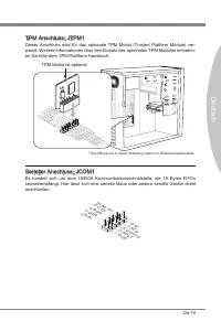
Page 63 - en Se btte dem TPM Plattform Handbuch.; TPM Modul st optonal; Sereller Anschluss: JCOM1
De-19 Deutsch TPM Anschluss: JTPM1 Deser Anschluss wrd für das optonale TPM Modul (Trusted Platform Module) ver- wendt. Wetere Informatonen über den Ensatz des optonalen TPM Modules entnehm- en Se btte dem TPM Plattform Handbuch. * Das MB-Layout n deser Abbldung haben nur Orenterungscharakter. 11 5 ...
Page 64 - Steckbrücke; Halten Se sch an de Anwesungen n der Grafik, um de Daten löschen.
De-20 MS-7640 Manboard Steckbrücke Steckbrücke zur CMOS- Löschung: JBAT1 Der Onboard CMOS Specher (RAM) wrd über ene zusätzlche Bettere mt Strom versorgt, um de Daten der Systemkonfiguraton zu spechern. Er ermöglcht es dem Betrebssystem, mt jedem Enschalten automatsch hochzufahren. Wenn Se de Sys- t...
Page 65 - brauch der Taste ändert.; OC Gene Taste: TURBO1; wederher; per/ Kühler mt OC Gene Funkton aus; Tasten
De-21 Deutsch Deser Abschntt beschrebt, we man de Funktonen des Motherboards durch den Ge- brauch der Taste ändert. OC Gene Taste: TURBO1 Dese Taste wrd zum Selbstübertaktung für das System benutzt. Drücken Se dese Taste, um der OC Gene Funkton zu ermöglchen, wenn das System m spannung- slosen Zusta...
Page 66 - Steckplätze; PCIE (Perpheral Component Interconnect Express) Steckplatz; Folge1 Folge2 Folge3 Folge4
De-22 MS-7640 Manboard Steckplätze PCIE (Perpheral Component Interconnect Express) Steckplatz Der PCIE-Steckplatz unterstützt ene Erweterungskarte mt der PCIE-Schnttstelle. PCIE x16-Steckplatz PCIE x1-Steckplatz PCI (Perpheral Component Interconnect) Steckplatz Der PCI-Steckplatz kann LAN-Karten, SC...
Page 70 - Se zum Aufruf des BIOS SETUP aufgefordert werden.; De erste Stellen den BIOS-Hersteller bezechnet, dabe glt E = EFI; Enterng Setup
De-26 MS-7640 Manboard BIOS Setup Deses Kaptel enthält Informatonen über das BIOS Setup und ermöglcht es Ihnen, Ihr System optmal auf Ihre Anforderungen enzustellen. Notwendgket zum Aufruf des BIOS besteht, wenn: Während des Bootvorgangs des Systems ene Fehlermeldung erschent und Se zum Aufruf des B...
Page 71 - Steuertasten
De-27 Deutsch Steuertasten Tastatur Maus Beschrebung <↑><↓> Bewegen Se den Cursor Auswahl enes Entrages <←><→> Auswahl enes Bldschrms <Enter> Klcken/ dop- pelt-klcken Se mt der lnken Maustaste Auswahl enes Symbols/ Feldes <Esc> Klcken Se mt der rechten Maustaste A...
Page 72 - Das Hauptmenü
De-28 MS-7640 Manboard Das Hauptmenü Nachdem Se das BIOS CMOS Setup Utlty, aufgerufen haben, erschent das Haupt- menü. Das Hauptmenü können Se von der Setup-Funktonen auswählen. Man Menu In desem Menü können Se de Basskonfiguraton Ihres Systems anpassen, so z.B. Uhrzet, Datum usw. Advanced Verwenden...
Page 73 - Systemlestung zu laden.
De-29 Deutsch Wenn Se das BIOS Denstprogramm öffnen, folgen Se den untenstehenden An- wesungen. Laden der gespecherten Werksenstellung : Durch de Steuertasten (←, →, ↑, ↓) können Se [Restore Defaults] n [Save & Ext]-Menü wählen und drücken Se auf <Engabe>. Und dann zegt der Bldschrm de fol...
Page 77 - Servce-Bassmenü : Mt desem Menü können Se offizelle Websete des MSI; für bessere System Lestung zu erhalten.
De-33 Deutsch Software-Informaton De m Manboard-Paket enthaltene DVD enthält alle notwendgen Treber. Um de Installaton automatsch laufen zu lassen, klcken Se enfach den Treber oder Utlty und folgen Se dem Pop-Up Schrm, um de Installaton durchzuführen. Der Treberge- brauchs-DVD enthält: Trebermenü : ...
Page 79 - Franças
Page 80 - Spécficatons
Fr-2 Carte mère MS-7640 Spécficatons Processeurs Supportés AMD ® Phenom TM II X6/ X4/ X3/ X2, Athlon TM II X4/ X3/ X2 et Sempron TM processeurs dans le paquet AM3+. (Pour plus d’nformaton sur le CPU, veullez vster http://www.ms.com/servce/cpu- support/) HyperTransport HyperTransport™ 3.0, supporte j...
Page 81 - França; Connecteurs
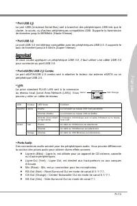
Fr-3 França s Connecteurs Panneau arrère 1 port claver PS/2 1 port sours PS/2 1 bouton d'effacement CMOS 1 port S/PDIF-Out coaxal 1 port S/PDIF-Out optque 4 ports USB 2.0 2 ports USB 3.0 2 ports eSATA/ USB 2.0 Combo 1 port LAN 1 port IEEE 1394 6 ports audo flexbles Connecteurs ntégrés 2 connecteurs ...
Page 82 - Gude Rapde Des Composants
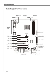
Fr-4 Carte mère MS-7640 S O C K E T A M 3 JPWR2, Fr-11 Gude Rapde Des Composants Panneau arrère, Fr-12 CPU, Fr-6 CPUFAN, Fr-15 DDR3, Fr-9 SYSFAN1, Fr-15 JPWR1, Fr-11 SYSFAN2, Fr-15 SATA1~6, Fr-14 JUSB3, Fr-18 SYSFAN4, Fr-15JTPM1, Fr-19 JFP1, JFP2, Fr-16 JBAT1, Fr-20 Panneau Debug LED, Fr-25 JUSB1/2,...
Page 83 - châsss qu entraînerat un court crcut à la carte mère.
Fr-5 França s S O C K E T A M 3 Trous Taraudés Quand vous nstallez la carte mère, l faut déposer la carte dans le châsss en bonne poston. La stuaton des trous taraudés sont montrée dans la figure c-dessous. Veullez vous référer à la figure pour nstaller le support dans une poston approprée sur le ch...
Page 84 - stallez-les avant d’allumer votre ordnateur.; Surchauffe; Introducton du AM3+ CPU; pour amélorer la dsspaton de la chaleur.
Fr-6 Carte mère MS-7640 Processeur : CPU Quand vous nstallez le CPU, veullez vous assurer d’nstaller un ventlateur pour évter la surchauffe. S vous n’en avez pas, contactez votre revendeu pour en acheter et n- stallez-les avant d’allumer votre ordnateur. Pour plus d’nformatons sur le CPU, veullez vs...
Page 85 - Installaton du CPU et son ventlateur
Fr-7 França s Installaton du CPU et son ventlateur Quand vous nstallez le CPU, assurez-vous que le CPU sot équpé d’un ventlateur de refrodssement attaché sur le dessus pour évter la surchauffe. Néanmons, n’oublez pas d’applquer une couche d’endut thermque sur le CPU avant d’nstaller le ventla- teur ...
Page 87 - d’nformatons sur les composants compatbles, veullez vster; du
Fr-9 França s Mémore Ces emplacements DIMM sont destnés à nstaller les modules de mémore. Pour plus d’nformatons sur les composants compatbles, veullez vster http://www.ms.com/ser- vce/test-report/ DDR3 240-pn, 1.5V 48x2=96 pn 72x2=144 pn Règle de populaton en mode double-canaux En mode de canaux-do...
Page 88 - Installaton des modules de mémore; du slot DIMM sur les côtés.; nséré dans le slot du DIMM.
Fr-10 Carte mère MS-7640 Installaton des modules de mémore Le module de mémore possède une seule encoche en son centre et ne s’adaptera que s’l est orenté de la mqnère convenable.Insérez le module de mémore à la vertcale dans le slot du DIMM. Poussez-le en- sute jusqu’à l’extrémté dorée du module de...
Page 89 - Connecteur d’almentaton ATX 24-pn : JPWR1; gouplles soent algnées. Enfoncez alors la prse dans le connecteur.; tons ATX pour garantr une opératon stable de la carte mère.
Fr-11 França s Connecteurs d’almentaton Connecteur d’almentaton ATX 24-pn : JPWR1 Ce connecteur vous permet de connecter l’almentaton ATX 24-pn. Pour cela, as- surez-vous que la prse d’almentaton est ben postonnée dans le bon sens et que les gouplles soent algnées. Enfoncez alors la prse dans le con...
Page 90 - Panneau arrère
Fr-12 Carte mère MS-7640 Panneau arrère Sours/Claver Le standard connecteur de sours/claver DIN de PS/2 ® est pour une sours ou un claver de PS/2 ® . Bouton d’effacement CMOS Il y a un CMOS RAM ntégré, qu possède un bloc d’almentaton almenté par une bat- tere externe, destné à conserver les données ...
Page 92 - être relé à un apparel de sére ATA.; pourraient se produire pendant la transmission; Connecteur Châsss Intruson : JCI1
Fr-14 Carte mère MS-7640 Connecteurs Connecteur Séral ATA : SATA1~6 Ce connecteur est un port d’nterface de sére ATA haut débt. Chaque connecteur peut être relé à un apparel de sére ATA. * Le schéma de carte mère dans la figure n’est qu’à ttre de référence. SATA5_6 SATA3_4 SATA1_2 SATA1~6 (6Gb/s) su...
Page 93 - afin de contrôler le ventlateur de l’unté centrale.
Fr-15 França s Connecteur d’almentaton du ventlateur : CPUFAN, SYSFAN1~4 Les connecteurs de courant du ventlateur supportent le ventlateur de refrodssement du système avec +12V. Lors du branchement des fils aux connecteurs, fates toujours en sorte que le fil rouge sot le fil postf devant être relé a...
Page 94 - trée/sorte du panneau avant Intel; Format) pour une transmsson audo numérque.
Fr-16 Carte mère MS-7640 Connecteur panneau avant : JFP1, JFP2 Ce connecteur est fourn pour la connecxon électrque aux nterrupteuts et LEDs du panneau avant. Le JFP1 est conforme au gude de concepton de la connectvté En- trée/sorte du panneau avant Intel ® . 1.Gro und 3.Su spen d LE D 5.Po wer L ED ...
Page 96 - Connecteur USB avant : JUSB3
Fr-18 Carte mère MS-7640 Connecteur USB avant : JUSB3 Le port USB 3.0 est nféreur-compatble avec les pérphérques USB 2.0. Il supporte le taux de transfert jusqu'à 5 Gbt/s (Super-Vtesse). 11 5 V 5.US B3_T X3_C _DN 4.Gro und 3.US B3_R X3_D P 2.US B3_R X3_D N 1.FU SB_V CC2 10.N C 9.SB D0+ 8.SB D0- 7.Gr...
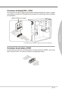
Page 97 - Connecteur de Module TPM : JTPM1; Module TPM est en opton; Connecteur de port séral : JCOM1; reçot 16 bytes FIFOs. Vous pouvez attacher un pérphérque séral.
Fr-19 França s Connecteur de Module TPM : JTPM1 Ce connecteur est rélé à TPM (Trusted Platform Module) Module (en opton). Veullez vous référer au manuel de TPM plat-forme (en opton) de sécurté pour plus de détals et d’utlsatons. * Le schéma de carte mère dans la figure n’est qu’à ttre de référence. ...
Page 98 - Cavalers; Cavaler d’effacement CMOS : JBAT1; cavaler pour effacer les données.; tème est allumé cela endommagerat la carte mère.
Fr-20 Carte mère MS-7640 Cavalers Cavaler d’effacement CMOS : JBAT1 Il y a un CMOS RAM ntégré, qu possède un bloc d’almentaton almenté par une bat- tere externe, destné à conserver les données de configuraton du système. Avec le CMOS RAM, le système peut lancer automatquement le système d’explotaton...
Page 99 - Bouton OC Gene : TURBO1; prochane ntalsaton; pour la dsspaton de la chaleur avec la foncton OC Gene; Bouton d’almentaton : POWER1; pour allumer ou étendre le système.; Bouton de réntalsaton : RESET1; Boutons
Fr-21 França s Cette secton vous explque comment changer la foncton de votre carte mère avec ces boutons c-dessous. Bouton OC Gene : TURBO1 Ce bouton sert à auto-overclocker pour le système. Appuyez sur ce bouton pour actver la foncton OC Gene lorsque le système est au statut étent, néanmons, le bou...
Page 100 - Emplacements; Emplacement PCIE (Perpheral Component Interconnect Express)
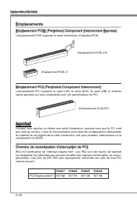
Fr-22 Carte mère MS-7640 Emplacements Emplacement PCIE (Perpheral Component Interconnect Express) L’emplacement PCIE supporte la carte d’extenson d’Interface PCIE. Emplacement PCIE x16 Emplacment PCIE x1 Emplacement PCI (Perpheral Component Interconnect) L’emplacement PCI supporte la carte LAN, la c...
Page 103 - Panneau Debug LED
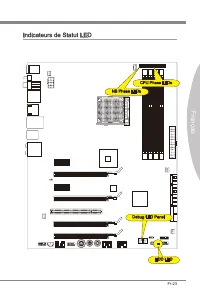
Fr-25 França s Panneau Debug LED Veullez vous référer au tableau c-dessous pour plus d’nformatons sur le message Debug LED. Poste Statut D1 Accomplr le test du contrôleur claver BAT. Vérfier s’l faut se réveller du mode velle de geston d’almentaton. Sauvegardr la valeur CPUID d’actvaton en sortant d...
Page 104 - Réglage BIOS; verson BIOS. Elle est généralement sous la forme :; Entrée dans le paramétrage
Fr-26 Carte mère MS-7640 Réglage BIOS Ce chaptre donne des nformatons concernant le programme de réglage de BIOS et vous permet de configurer le système pour obtenr des performances d’utlsaton opt- mum. Vous aurez peut-être beson de lancer le programme de réglage quand : Un message d’erreur apparaît...
Page 105 - Contrôle
Fr-27 França s Contrôle Claver Sours Descrpton <↑><↓> Bouger le cur- seur Chosr un artcle <←><→> Chosr un écran <Entrer> Clquer/ Double- clquer le bouton gauche Chosr une cône/ un domane <Esc> Clquer le bou- ton drote Retourner au menu Ext ou revenr à la page préc...
Page 106 - Menu prncpal
Fr-28 Carte mère MS-7640 Menu prncpal Une fos entré dans l’unté de réglages BIOS CMOS, le menu prncpal apparaît sur l’écran. Le Menu Prncpal vous permet de sélectonner parm les fonctons de réglag- es. Man Menu Utlsez ce menu pour les configuratons du système de base, tel que l’heure, la date. Advanc...
Page 107 - pour l’utlsaton générale.
Fr-29 França s Quand vous entrez dans l’unté de réglages BIOS, suvez les procédures suvantes pour l’utlsaton générale. Load Optmzed Defaults (Chargement des réglages optmsés par défaut) : Utlsez les touches de flèche (←, →, ↑, ↓) pour chosr [Restore Defaults] dans le menu [Save & Ext], et appuye...
Page 111 - hatez pour actver le dspostf.; melleure performance du système.
Fr-33 França s Informaton Logcel Sortez le DVD Plote/ Servce, qu est nclus dans la boîte de la carte mère et placez-le dans le DVD-ROM. L’nstallaton va automatquement se déclencher, clquez sur le p- lote ou sur l’utltare et suvez le pop-up de l’écran pour accomplr l’nstallaton. Le DVD de Plote/Servc...
Page 113 - Русский
Page 114 - Характеристики
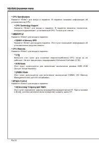
Ru-2 MS-7640 Системная плата Характеристики Процессоры Процессоры AMD ® Phenom TM II X6/ X4/ X3/ X2, Athlon TM II X4/ X3/ X2 и Sempron TM в конструктиве AM3+ . (Для получения самой новой информации о CPU, посетите сайт http://www.ms.com/servce/cpu-support/) HyperTransport HyperTransport™ 3.0, поддер...
Page 115 - Коннекторы
Ru-3 Русский Коннекторы Задней панели 1 PS/2 порт клавиатуры 1 PS/2 порт мыши 1 кнопка сброс CMOS 1 порт коаксиального S/PDIF-Out 1 порт оптического S/PDIF-Out 4 порта USB 2.0 2 порта USB 3.0 2 порта eSATA/ USB 2.0 Combo 1 порт LAN 1 порт IEEE 1394 6 звуковых разъемов с гибким переназначением Разъем...
Page 116 - Размещение компонентов системной платы
Ru-4 MS-7640 Системная плата S O C K E T A M 3 JPWR2, Ru-11 Размещение компонентов системной платы Задняя панель, Ru-12 CPU, Ru-6 CPUFAN, Ru-15 DDR3, Ru-9 SYSFAN1, Ru-15 JPWR1, Ru-11 SYSFAN2, Ru-15 SATA1~6, Ru-14 JUSB3, Ru-18 SYSFAN4, Ru-15JTPM1, Ru-19 JFP1, JFP2, Ru-16 JBAT1, Ru-20 Debug LED Panel,...
Page 117 - направлении. Размещения отверстий для винтов показаны ниже.; Внимание; Отверстия для винтов
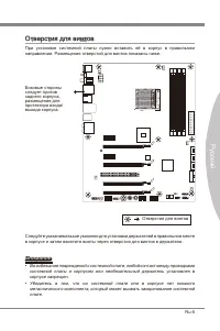
Ru-5 Русский S O C K E T A M 3 Отверстия для винтов При установке системной платы нужно вставить её в корпус в правильном направлении. Размещения отверстий для винтов показаны ниже. Следуйте указаниям выше указанно для установки держателей в правильном месте в корпусе и затем ввинтите винты через от...
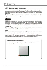
Page 118 - Перегрев; Внешний вид процессора AM3+; теплопроводящей пасты на процессоре.
Ru-6 MS-7640 Системная плата CPU (Центральный процессор) При установке CPU, чтобы уберечь процессор от перегрева, не забудьте установить процессорный кулер. Если у вас нет процессорного кулера, пожалуйста, свяжитесь с дилером с целью приобретения и его установки до того, как включите компьютер. Посл...
Page 119 - Установка процессора и вентилятора
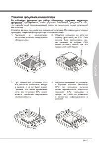
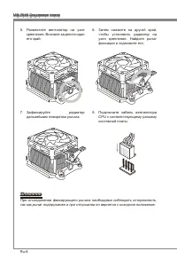
Ru-7 Русский Установка процессора и вентилятора Во избежание перегрева при работе обязательно установите вентилятор процессора. Одновременно, чтобы улучшить теплоотвод, убедитесь в том, что нанесён слой теплопроводящей пасты на процессоре перед установкой вентилятора. Следуйте данным указаниям для п...
Page 122 - Установка модулей памяти
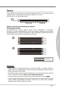
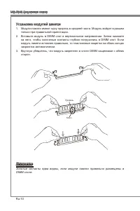
Ru-10 MS-7640 Системная плата Установка модулей памяти Модули памяти имеют одну прорезь в средней части. Модуль войдет в разьем только при правильной ориентации.Вставьте модуль в DIMM слот в вертикальном направлении. Затем нажмите на него, чтобы золоченые контакты глубоко погрузились в DIMM слот. Ес...
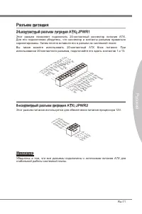
Page 123 - Вы также можете использовать 20-контактный ATX блок питания. При; стабильной работы системной платы.
Ru-11 Русский Разъем питания 24-контактный разъем питания ATX: JPWR1 Этот разъем позволяет подключить 24-контактный коннектор питания ATX. Для его подключения убедитесь, что коннектор и контакты разъема правильно сориентированы. Затем плотно вставьте его в разъем на системной плате. Вы также можете ...
Page 124 - Задняя панель
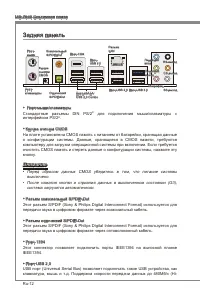
Ru-12 MS-7640 Системная плата Задняя панель Порт мыши/клавиатуры Стандартные разъемы DIN PS/2 ® для подключения мыши/клавиатуры с интерфейсом PS/2 ® . Кнопка очистка CMOS На плате установлена CMOS память с питанием от батарейки, хранящая данные о конфигурации системы. Данные, хранящиеся в CMOS памят...
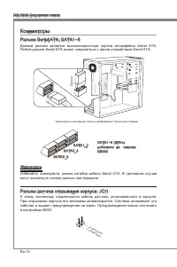
Page 126 - работают на чипсете; могут возникнуть потери данных при передаче.; Разъем датчика открывания корпуса: JCI1
Ru-14 MS-7640 Системная плата Коннекторы Разъем Seral ATA: SATA1~6 Данный разъем является высокоскоростным портом интерфейса Seral ATA. Любой разъем Seral ATA может соединяться с одним устройством Seral ATA. * Компоненты системной платы в изображении только для справки. SATA5_6 SATA3_4 SATA1_2 SATA1...
Page 127 - панели и соответствует руководству Intel
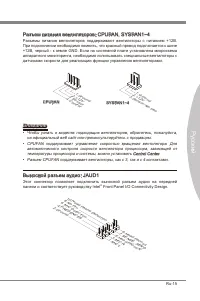
Ru-15 Русский Разъем питания вентиляторов: CPUFAN, SYSFAN1~4 Разъемы питания вентиляторов поддерживают вентиляторы с питанием +12В. При подключении необходимо помнить, что красный провод подключается к шине +12В, черный - к земле GND. Если на системной плате установлена микросхема аппаратного монито...
Page 128 - руководству Intel; Dgtal Interconnect Format) для передачи звука в цифровом формате.
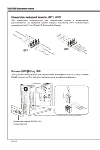
Ru-16 MS-7640 Системная плата Коннекторы передней панели: JFP1, JFP2 Эти коннекторы используются для подключения кнопок и индикаторов, расположенных на передней панели корпуса. Коннектор JFP1 соответствует руководству Intel ® Front Panel I/O Connectvty Desgn. 1.Gro und 3.Su spen d LE D 5.Po wer L ED...
Page 130 - Разъем USB передней панели: JUSB3; Выносная планка USB 3.0
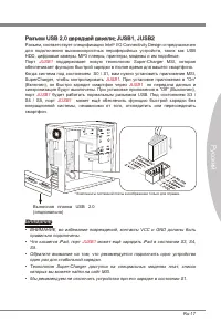
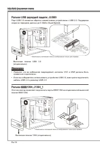
Ru-18 MS-7640 Системная плата Разъем USB передней панели: JUSB3 Порт USB 3.0 является обратно совместимым устройством с USB 2.0. Поддержка скорости передачи данных до 5 Gbt/s (SuperSpeed). 11 5 V 5.US B3_T X3_C _DN 4.Gro und 3.US B3_R X3_D P 2.US B3_R X3_D N 1.FU SB_V CC2 10.N C 9.SB D0+ 8.SB D0- 7....
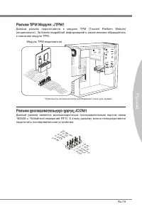
Page 131 - Разъем TPM Модуля: JTPM1; Данный разъем подключается к модулю TPM (Trusted Platform Module); Модуль TPM опционально; Разъем последовательного порта: JCOM1; подключить последовательное устройство.
Ru-19 Русский Разъем TPM Модуля: JTPM1 Данный разъем подключается к модулю TPM (Trusted Platform Module) (опционально). За более подробной информацией и назначениями обращайтесь к описанию модуля TPM. * Компоненты системной платы в изображении только для справки. 11 5 V 10.N o Pin 14.G roun d 8.5V P...
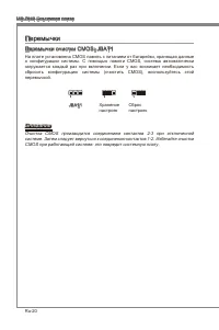
Page 132 - Перемычки; Перемычки очистки CMOS: JBAT1; Хранение; CMOS при работающей системе: это повредит системную плату.
Ru-20 MS-7640 Системная плата Перемычки Перемычки очистки CMOS: JBAT1 На плате установлена CMOS память с питанием от батарейки, хранящая данные о конфигурации системы. С помощью памяти CMOS, система автоматически загружается каждый раз при включении. Если у вас возникает необходимость сбросить конфи...
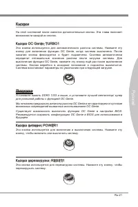
Page 133 - Кнопка OC Gene: TURBO1; Кнопки
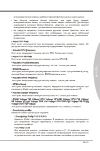
Ru-21 Русский На этой системной плате имеются дополнительные кнопки. Эта глава поясняет возможности каждой из кнопок. Кнопка OC Gene: TURBO1 Эта кнопка используется для автоматического разгона системы. Нажмите эту кнопку для включения функции OC Gene, когда система выключена. После нажатия кнопка фи...
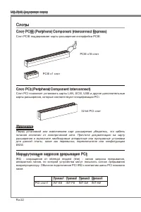
Page 134 - Слоты; Слот PCIE (Perpheral Component Interconnect Express); Слот PCIE поддерживает карты расширения интерфейса PCIE.; Слот PCI (Perpheral Component Interconnect); карты расширения, которые соответствуют спецификации PCI.; Приказ1 Приказ2 Приказ3 Приказ4
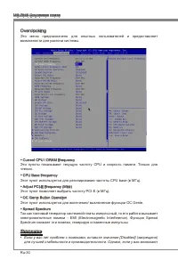
Ru-22 MS-7640 Системная плата Слоты Слот PCIE (Perpheral Component Interconnect Express) Слот PCIE поддерживает карты расширения интерфейса PCIE. PCIE x16 слот PCIE x1 слот Слот PCI (Perpheral Component Interconnect) Слот PCI позволяет установить карты LAN, SCSI, USB и другие дополнительные карты ра...
Page 136 - Панель индикатора фаз CPU (CPU Phase LED panel)
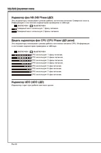
Ru-24 MS-7640 Системная плата Индикатор фаз NB (NB Phase LED) Эти индикаторы показывают режим работы источника питания Северного моста. Информация о состоянии индикаторов приведена в таблице. ВКЛЮЧЕН ВЫКЛЮЧЕН Северный мост использует 1 фазу питания. Северный мост использует 2 фазы питания. Панель ин...
Page 137 - Панель индикаторов загрузки (Debug LED Panel)
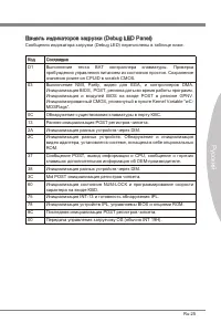
Ru-25 Русский Панель индикаторов загрузки (Debug LED Panel) Сообщения индикатора загрузки (Debug LED) перечислены в таблице ниже. Код Состояние D1 Выполнение теста BAT контраллера клавиатуры. Проверка пробуждения управления питанием из состояния простоя. Сохранение значения power-on CPUID в scratch ...
Page 138 - Настройка BIOS
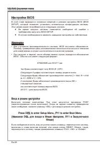
Ru-26 MS-7640 Системная плата Настройка BIOS В этой главе приводятся основные сведения о режиме настройки BIOS (BIOS SETUP), который позволяет установить оптимальную конфигурацию системы. Этот режим может потребоваться в следующих случаях: Во время загрузки системы появляется сообщение об ошибке с т...
Page 139 - Контроль
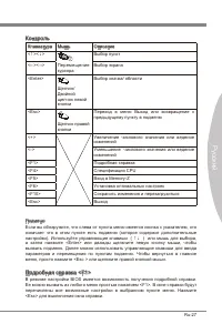
Ru-27 Русский Контроль Клавиатура Мышь Описание <↑><↓> Перемещение курсора Выбор пункт <←><→> Выбор экрана <Enter> Щелчок/ Двойной щелчок левой кнопки Выбор значка/ области <Esc> Щелчок правой кнопки Переход в меню Выход или возвращение к предыдущему пункту в подм...
Page 141 - умолчанию для оптимальной производительности системы.
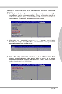
Ru-29 Русский Находясь в режиме настройки BIOS, рекомендуется выполнить следующие действия. Load Optmzed Defaults : Клавишами стрелки (←, →, ↑, ↓) выберите пункт [Re- store Defaults] из меню [Save & Ext], нажмите <Enter>. И на экране появляется сообщение, выберите [Yes] и нажмите <Enter...
Page 145 - Установите драйверы для подключения необходимых устройств.; BIOS, которые позволят улучшить производительность системы.
Ru-33 Русский Сведения о программном обеспечении Установите в привод диск Drver/Utlty (Драйверы и утилиты) из комплекта поставки системной платы. Автоматически запустится инсталляция. Нажмите на название драйвера/ утилиты и следуйте инструкциям на экране для завершения инсталляции. Диск Drver/Utlty ...


 MSI 651M-V
User Manual
MSI 651M-V
User Manual
 MSI MS-7304
User Manual
MSI MS-7304
User Manual
 MSI 870-C45 V2series
User Manual
MSI 870-C45 V2series
User Manual
 MSI StarCam mini
User Manual
MSI StarCam mini
User Manual
 MSI AP16 Flex-SJ1904G32DX81MGMXH
User Manual
MSI AP16 Flex-SJ1904G32DX81MGMXH
User Manual
 MSI 970A-G45
User Manual
MSI 970A-G45
User Manual
 MSI MEGA 865 PRO MS-6287
User Manual
MSI MEGA 865 PRO MS-6287
User Manual
-User-Manual/webp/1.webp) MSI Z68MA-ED55 (B3)
User Manual
MSI Z68MA-ED55 (B3)
User Manual
 MSI EC14H
User Manual
MSI EC14H
User Manual
-OC-Guide-User-Manual/webp/1.webp) MSI P67A-GD65 (B3) OC Guide
User Manual
MSI P67A-GD65 (B3) OC Guide
User Manual
 MSI J1800TI
User Manual
MSI J1800TI
User Manual
-User-Manual/webp/1.webp) MSI PH61-P33 (B3)
User Manual
MSI PH61-P33 (B3)
User Manual
 MSI Z97-GD65 GAMING Manual
User Manual
MSI Z97-GD65 GAMING Manual
User Manual
-User-Manual/webp/1.webp) MSI Z68A-GD55 (G3)
User Manual
MSI Z68A-GD55 (G3)
User Manual
 MSI B85-G43
User Manual
MSI B85-G43
User Manual
 MSI MS-7199
User Manual
MSI MS-7199
User Manual
-User-Manual/webp/1.webp) MSI MS-9A35 (WindBOX III)
User Manual
MSI MS-9A35 (WindBOX III)
User Manual
-User-Manual/webp/1.webp) MSI H67MA-E45 (B3)
User Manual
MSI H67MA-E45 (B3)
User Manual
-User-Manual/webp/1.webp) MSI X79A-GD45 (8D)
User Manual
MSI X79A-GD45 (8D)
User Manual