Makita DA4000LR - Manuals
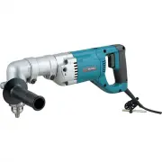
User Manual Makita DA4000LR


Summary
2 SPECIFICATIONS • Manufacturer reserves the right to change specifications without notice. • Specifications may differ from country to country. GENERAL SAFETY RULES USA002-2 (For All Tools) WARNING: Read and understand all instructions. Failure to follow all instructions listed below, may result in...
5 SPECIFIC SAFETY RULES USB001-2 DO NOT let comfort or familiarity with product (gained fromrepeated use) replace strict adherence to drill safety rules. Ifyou use this tool unsafely or incorrectly, you can suffer seriouspersonal injury. 1. Hold tool by insulated gripping surfaceswhen performing an ...
6 SYMBOLS USD201-2 The followings show the symbols used for tool. V ....................... volts A ....................... amperes Hz ..................... hertz ................ alternating current .................... no load speed .................... Class II Construction .../min .................
Manual Makita DA4000LR


Summary
2 SPECIFICATIONS • Manufacturer reserves the right to change specifications without notice. • Specifications may differ from country to country. GENERAL SAFETY RULES USA002-2 (For All Tools) WARNING: Read and understand all instructions. Failure to follow all instructions listed below, may result in...
5 SPECIFIC SAFETY RULES USB001-2 DO NOT let comfort or familiarity with product (gained fromrepeated use) replace strict adherence to drill safety rules. Ifyou use this tool unsafely or incorrectly, you can suffer seriouspersonal injury. 1. Hold tool by insulated gripping surfaceswhen performing an ...
6 SYMBOLS USD201-2 The followings show the symbols used for tool. V ....................... volts A ....................... amperes Hz ..................... hertz ................ alternating current .................... no load speed .................... Class II Construction .../min .................
Makita Drills Manuals
-
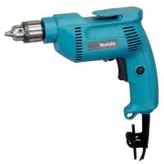 Makita 6407
User Manual
Makita 6407
User Manual
-
Makita 6407
Manual
-
 Makita 6501
User Manual
Makita 6501
User Manual
-
Makita 6501
Manual
-
 Makita 6300-4
User Manual
Makita 6300-4
User Manual
-
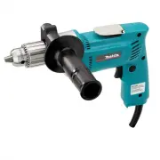 Makita 6302H
User Manual
Makita 6302H
User Manual
-
Makita 6302H
Manual
-
 Makita 6408K
User Manual
Makita 6408K
User Manual
-
Makita 6408K
Manual
-
 Makita DA4031
User Manual
Makita DA4031
User Manual
-
Makita DA4031
Manual
-
 Makita DDA350Z
User Manual
Makita DDA350Z
User Manual
-
 Makita DP2010
User Manual
Makita DP2010
User Manual
-
 Makita DP3003
User Manual
Makita DP3003
User Manual
-
Makita DP3003
Manual
-
 Makita DP4000
User Manual
Makita DP4000
User Manual
-
Makita DP4000
Manual
-
 Makita DP4001
User Manual
Makita DP4001
User Manual
-
Makita DP4001
Manual
-
 Makita DP4003
User Manual
Makita DP4003
User Manual