LG F1256QD - Manuals
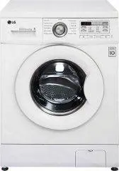
LG F1256QD Washing Machine – Manual in PDF format online.
Manuals:
Manual LG F1256QD


Summary
2 CONTENTS 1. SPECIFICATIONS ............................................................................................................................. 3 2. FEATURES & TECHNICAL EXPLANATION ..................................................................................... 4 3. PARTS IDENTI...
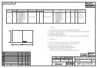
3 1. SPECIFICATION ITEM F1*20TD(1~9) / F1*22TD(1~9)/F1*56*D/WD-*690TDK POWER SUPPLY PRODUCT WEIGHT OPERATION WATER PRESSURE CONTROL TYPE WASH CAPACITY DIMENSION DOOR SWITCH TYPE WATER LEVEL DELAY FINISH TIME SENSING OF THE LAUNDRY AMOUNT FUZZY LOGIC DISPLAY OF THE REMAINING TIME ERROR DIAGNOSIS POWE...
5 2-2. DETERMINE WASHING TIME BY FUZZY LOGIC To get the best washing performance optimal time is determined by sensing of water temperature,selected washing temperature and laundry amount. 2-3. WATER LEVEL CONTROL This model uses a pressure sensor to determine the water level in the tub. When the pr...
LG Washing Machines Manuals
-
 LG F10B8LD0
Manual
LG F10B8LD0
Manual
-
 LG F10B8QD
Manual
LG F10B8QD
Manual
-
 LG F1443KDS
Manual
LG F1443KDS
Manual
-
 LG F4J6VN0W
Manual
LG F4J6VN0W
Manual
-
 LG F80B8MD
Manual
LG F80B8MD
Manual
-
 LG FH2C3WD
Manual
LG FH2C3WD
Manual
-
 LG FH2H3WDS2
Manual
LG FH2H3WDS2
Manual
-
 LG SWWE50N3
User Manual
LG SWWE50N3
User Manual
-
LG SWWG50N3
User Manual
-
 LG TW4V9RD9E
Manual
LG TW4V9RD9E
Manual
-
 LG WD1013NDW
User Manual
LG WD1013NDW
User Manual
-
 LG WD1200D
User Manual
LG WD1200D
User Manual
-
 LG WD12021D6
User Manual
LG WD12021D6
User Manual
-
 LG WD1207NCW
User Manual
LG WD1207NCW
User Manual
-
 LG WD1275TC5W
User Manual
LG WD1275TC5W
User Manual
-
 LG WD14022D6
User Manual
LG WD14022D6
User Manual
-
 LG WD14023D6
User Manual
LG WD14023D6
User Manual
-
 LG WD14024D6
User Manual
LG WD14024D6
User Manual
-
 LG WD14071SD6
User Manual
LG WD14071SD6
User Manual
-
 LG WD1408NCW
User Manual
LG WD1408NCW
User Manual