KOBE IN2636SQB-700-1 - Manuals
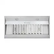
User Manual KOBE IN2636SQB-700-1


Summary
IMPORTANT READ THIS FIRST READ BEFORE INSTALLATION 1. Carefully check all contents of package(s). 2. Thoroughly inspect the unit for any shipping damages, cosmetic damages or defects. 3. Have a certified contractor/electrician test the unit before installation. IF THERE IS ANY PROBLEM: 1. DO NOT INS...
[ENGLISH] - READ AND SAVE THESE INSTRUCTIONS - CONTENTS IMPORTANT SAFETY INSTRUCTIONS .................................................................................... 1 COMPONENTS OF PACKAGE ................................................................................................. 3 INSTA...
1 IMPORTANT SAFETY INSTRUCTIONS - PLEASE READ THIS SECTION CAREFULLY BEFORE INSTALLATION - WARNING : TO REDUCE THE RISK OF FIRE, ELECTRIC SHOCK OR PERSONAL INJURY, OBSERVE THE FOLLOWING: 1) Installation and electrical wiring must be done by qualified professionals and in accordance with all applicab...
KOBE Range Hoods Manuals
-
 KOBE CH2230SQB6-XX
User Manual
KOBE CH2230SQB6-XX
User Manual
-
 KOBE CH2236SQB6-XX
User Manual
KOBE CH2236SQB6-XX
User Manual
-
 KOBE CH7748SQ6-WM-XX
User Manual
KOBE CH7748SQ6-WM-XX
User Manual
-
 KOBE CH7748SQ6-XX
User Manual
KOBE CH7748SQ6-XX
User Manual
-
 KOBE CHX2230SQB-1
User Manual
KOBE CHX2230SQB-1
User Manual
-
 KOBE CHX2236SQB-1
User Manual
KOBE CHX2236SQB-1
User Manual
-
 KOBE CHX3830SQBD-3
User Manual
KOBE CHX3830SQBD-3
User Manual
-
 KOBE CHX3836SQBD-3
User Manual
KOBE CHX3836SQBD-3
User Manual
-
 KOBE CHX8130SQB-1
User Manual
KOBE CHX8130SQB-1
User Manual
-
 KOBE CHX9130SQB-1
User Manual
KOBE CHX9130SQB-1
User Manual
-
 KOBE CHX9130SQB-2
User Manual
KOBE CHX9130SQB-2
User Manual
-
 KOBE CHX9136SQB-1
User Manual
KOBE CHX9136SQB-1
User Manual
-
 KOBE IN2630SQB-700-2
User Manual
KOBE IN2630SQB-700-2
User Manual
-
 KOBE IN2636SQB-1200-1
User Manual
KOBE IN2636SQB-1200-1
User Manual
-
 KOBE IN2830SQB-XX
User Manual
KOBE IN2830SQB-XX
User Manual
-
 KOBE IN2830SQP-XX
User Manual
KOBE IN2830SQP-XX
User Manual
-
 KOBE IN2836SQP-XX
User Manual
KOBE IN2836SQP-XX
User Manual
-
 KOBE INX2630SQB-700-3
User Manual
KOBE INX2630SQB-700-3
User Manual
-
 KOBE INX2636SQB-700-3
User Manual
KOBE INX2636SQB-700-3
User Manual
-
 KOBE INX2730SQB-700-3
User Manual
KOBE INX2730SQB-700-3
User Manual