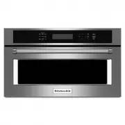
KitchenAid KMLS311HBS - Manuals
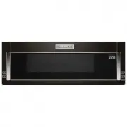
KitchenAid KMLS311HBS Microwave – User Manual, Installation Manual, Manual in PDF format online.
Manuals:
User Manual KitchenAid KMLS311HBS


Installation Manual KitchenAid KMLS311HBS


Summary
2 INSTALLATION REQUIREMENTS Tools and Parts Tools needed Gather the required tools and parts before starting installation. Read and follow the instructions provided with any tools listed here. ■ Measuring tape ■ Pencil ■ Masking tape or thumbtacks ■ Scissors ■ No. 3 Phillips screwdriver for ¼- 20 x ...
3 Installation Dimensions NOTE: The grounded 3 prong outlet must be inside the upper cabinet. See the “Electrical Requirements” section. *24” (61 cm) is typical for 60” (152.4 cm) installation height. Exact dimensions may vary depending on type of range/ cooktop below. Product Dimensions *Overall de...
4 Wall Venting Installation Only 1. Using diagonal wire cutting pliers, gently snip out the rectangular vent cover on the damper plate. Install Damper Assembly (for wall venting only) 1. Check th at damper blade moves freely, and opens fully. 2. Position the damper assembly on the back of the microw...
Manual KitchenAid KMLS311HBS


KitchenAid Microwaves Manuals
-
 KitchenAid KMBD104GSS
User Manual
KitchenAid KMBD104GSS
User Manual
-
KitchenAid KMBD104GSS
Installation Manual
-
KitchenAid KMBD104GSS
Manual
-
KitchenAid KMBD104GSS
Troubleshooting Guide
-
 KitchenAid KMBP100EBS
User Manual
KitchenAid KMBP100EBS
User Manual
-
KitchenAid KMBP100EBS
Manual
-
KitchenAid KMBP100EBS
Installation Manual
-
 KitchenAid KMBP100ESS
User Manual
KitchenAid KMBP100ESS
User Manual
-
KitchenAid KMBP100ESS
Manual
-
KitchenAid KMBP100ESS
Installation Manual
-
 KitchenAid KMBP107EBS
User Manual
KitchenAid KMBP107EBS
User Manual
-
KitchenAid KMBP107EBS
Manual
-
KitchenAid KMBP107EBS
Installation Manual
-
 KitchenAid KMBP107ESS
User Manual
KitchenAid KMBP107ESS
User Manual
-
KitchenAid KMBP107ESS
Manual
-
KitchenAid KMBP107ESS
Installation Manual
-
 KitchenAid KMBS104EBL
User Manual
KitchenAid KMBS104EBL
User Manual
-
KitchenAid KMBS104EBL
Installation Manual
-
KitchenAid KMBS104EBL
Manual
-
 KitchenAid KMBS104ESS
User Manual
KitchenAid KMBS104ESS
User Manual