Page 2 - Your safety and the safety of others are very important.; DANGER
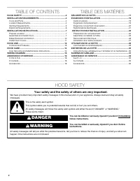
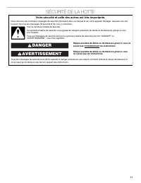
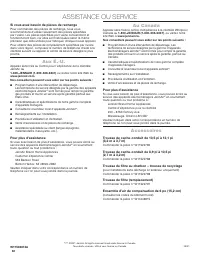
2 TABLE OF CONTENTS TABLE DES MATIÈRES HOOD SAFETY You can be killed or seriously injured if you don't immediately You can be killed or seriously injured if you don't follow All safety messages will tell you what the potential hazard is, tell you how to reduce the chance of injury, and tell you what...
Page 3 - IMPORTANT SAFETY INSTRUCTIONS; READ AND SAVE THESE INSTRUCTIONS
3 IMPORTANT SAFETY INSTRUCTIONS READ AND SAVE THESE INSTRUCTIONS For General Ventilating Use Only. Do Not Use To Exhaust Hazardous Or Explosive Materials And Vapors. This appliance is not intended for use by people (including children) whose physical, sensory or mental capacities are different or im...
Page 4 - INSTALLATION REQUIREMENTS; Tools and Parts; Location Requirements
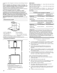
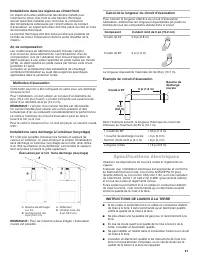
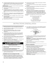
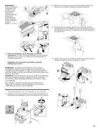
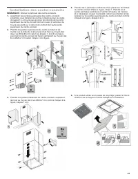
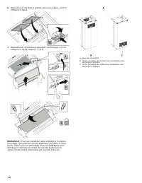
4 INSTALLATION REQUIREMENTS Tools and Parts Gather the required tools and parts before starting installation. Read and follow the instructions provided with any tools listed here. Tools needed ■ Level ■ Drill with 1¼" (3 cm), 3/8" (9.5 mm), 7/64" (2.75 mm) and 1/8" (3 mm) drill bits ...
Page 5 - Venting Requirements
5 Installation Dimensions IMPORTANT: Minimum distance “C”: 30" (76.2 cm) from electric cooking surface.Minimum distance “C”: 30" (76.2 cm) from gas cooking surface.Suggested maximum distance “C”: 36" (91.4 cm)The chimneys can be adjusted for different ceiling heights. See the following c...
Page 6 - Electrical Requirements
6 For Non-Vented (recirculating) Installations If it is not possible to vent cooking fumes and vapors to the outside, the hood can be used in the non-vented (recirculating) version, fitting a charcoal filter and the deflector. Fumes and vapors are recycled through the top grille. Roof venting Non-ve...
Page 7 - INSTALLATION INSTRUCTIONS; Prepare Location; WARNING; Assemble and Install Hood
7 INSTALLATION INSTRUCTIONS Prepare Location ■ It is recommended that the vent system be installed before the hood is installed. ■ Before making cutouts, make sure there is proper clearance within the ceiling for exhaust vent. ■ Hood is to be installed 30" (76.2 cm) minimum for electric cooking ...
Page 10 - Make Electrical Connection
10 Non-Vented (Recirculating) Installations: Connect the flexible hose to the air diverter and fix it with a clamp (not supplied) as shown in figure. Make Electrical Connection WARNING Electrical Shock Hazard Disconnect power before servicing.Replace all parts and panels before operating.Failure to ...
Page 11 - Install Duct Covers
11 7. Connect green (or bare) ground wire from home power supply to yellow-green ground wire (F) in terminal box using UL listed wire connectors. 8. Tighten strain relief screw. 9. Install terminal box cover. 10. Check that all light bulbs are secure in their sockets. 11. Reconnect power. Optional P...
Page 13 - HOOD USE; Controls and Features
13 HOOD USE The hood is designed to remove smoke, cooking vapors and odors from the cooktop area. For best results, start the hood before cooking and allow it to operate several minutes after the cooking is complete to clear all smoke and odors from the kitchen.The hood controls are located on the f...
Page 14 - HOOD CARE; User Servicing and Maintenance Instructions
14 Timer The hood can be set to turn Off automatically after 15 minutes. 1. Press and hold the desired fan speed button for 2 seconds.The fan will run on the chosen speed for 15 minutes, and the fan speed button light will flash continuously.After 15 minutes, the fan will turn Off automatically. 2. ...
Page 15 - WIRING DIAGRAM
Page 16 - ASSISTANCE OR SERVICE; In Canada; Accessories
16 ASSISTANCE OR SERVICE If you need replacement parts If you need to order replacement parts, we recommend that you use only factory specified parts. Factory specified parts will fit right and work right because they are made with the same precision used to build every new appliance.To locate facto...
Page 17 - SÉCURITÉ DE LA HOTTE; Votre sécurité et celle des autres est très importante.; AVERTISSEMENT
17 SÉCURITÉ DE LA HOTTE Risque possible de décès ou de blessure grave si vous ne suivez pas immédiatement les instructions. Risque possible de décès ou de blessure grave si vous ne suivez pas les instructions. Tous les messages de sécurité vous diront quel est le danger potentiel et vous disent comm...
Page 18 - IMPORTANTES INSTRUCTIONS DE SÉCURITÉ; LIRE ET CONSERVER CES INSTRUCTIONS
18 IMPORTANTES INSTRUCTIONS DE SÉCURITÉ LIRE ET CONSERVER CES INSTRUCTIONS AVERTISSEMENT : POUR RÉDUIRE LE RISQUE D'INCENDIE, CHOC ÉLECTRIQUE OU DOMMAGES CORPORELS, RESPECTER LES INSTRUCTIONS SUIVANTES : ■ Utiliser cet appareil uniquement dans les applications envisagées par le fabricant. Pour toute...
Page 19 - EXIGENCES D’INSTALLATION; Outils et pièces; Exigences d’emplacement
19 EXIGENCES D’INSTALLATION Outils et pièces Rassembler les outils et pièces nécessaires avant d’entreprendre l’installation. Lire et observer les instructions fournies avec chacun des outils de la liste ci-dessous. Outils nécessaires ■ Niveau ■ Perceuse avec forets de 1 ¼ po (3 cm), 3/8 po (9,5 mm)...
Page 20 - Exigences concernant
20 Cette hotte a été configurée à l’usine pour une décharge à travers le toit.Pour une installation sans décharge à l’extérieur (recyclage), voir le point « Installations sans décharge à l’extérieur (recyclage) » à la section « Assembler et installer la hotte ». La trousse de recyclage (numéro de pi...
Page 21 - Spécifications électriques
21 Installations dans les régions au climat froid Un clapet anti-reflux additionnel devrait être installé pour minimiser le reflux d’air froid et une barrière thermique devrait aussi être installée pour minimiser la conduction des températures extérieures par l’intermédiaire du conduit d’évacuation....
Page 22 - INSTRUCTIONS D’INSTALLATION; Préparation de l’emplacement
22 ■ Cet appareil doit être relié à la terre. Au cas où un court-circuit se produirait, la liaison à la terre réduit le risque de choc électrique en permettant au courant de s’échapper directement vers la terre. AVERTISSEMENT : Une mise à la terre incorrecte peut entraîner un risque de choc électriq...
Page 23 - Assembler et installer la hotte
23 REMARQUE : Pour une meilleure manipulation de la hotte, avant de procéder à l’installation, retirer le panneau d’aspiration périphérique et le filtre à graisse, comme indiqué à la figure, étapes 1, 2, 3 et 4. 3. Pour les installations avec décharge à l’extérieur uniquement : À l’aide d’une scie s...
Page 26 - Raccordement électrique
26 Raccordement électrique AVERTISSEMENT Risque de choc électrique Déconnecter la source de courant électrique avant l'entretien.Replacer pièces et panneaux avant de faire la remise en marche.Le non-respect de ces instructions peut causer un décès ou un choc électrique. 1. Débrancher l’alimentation....
Page 27 - Installation des cache-conduits
27 Installation des cache-conduits REMARQUE : Enlever la pellicule des cache-conduits. 1. Assembler les parties supérieures des cache-conduits ensemble, puis installer les cache-conduits autour du cadre de support. Le trou le plus gros sur les rebords de la partie supérieure du cache-conduit doit se...
Page 29 - UTILISATION DE LA HOTTE; Commandes et caractéristiques
29 UTILISATION DE LA HOTTE La hotte est conçue pour extraire fumée, vapeurs de cuisson et odeurs de la zone de la table de cuisson. Pour des résultats optimaux, mettre la hotte en marche avant d’entreprendre une cuisson, et la laisser fonctionner pendant plusieurs minutes après une cuisson afin d’év...
Page 30 - ENTRETIEN DE LA HOTTE; Instructions aux utilisateurs sur l’entretien et la maintenance
30 Minuterie La hotte peut être réglée pour s’éteindre automatiquement après 15 minutes. 1. Maintenir appuyé le bouton de la vitesse de ventilateur désirée pendant 2 secondes.Le moteur du ventilateur fonctionne alors à la vitesse sélectionnée pendant 15 minutes et le témoin lumineux de la vitesse du...
Page 31 - SCHÉMA DE CÂBLAGE
31 SCHÉMA DE CÂBLAGE JA/VE NOIR GRIS BLANC JA/VE NOIR NOIR JA/VE BLANC FILTRE R.F.I. JAUNE MARRON ROUGE BLEU BLANC CARTE PRINCIPALE BLANC - 1 NOIR - 3 GRIS - 3 ROUGE - 4 BLEU - 5 BLANC - 2NOIR - 1 INTERFACE UTILISATEUR NOIR ROUGE MARRON ROUGE PILOTE DEL MARRON - 1 ROUGE - 3 BARRE DEL BARRE DEL NOIR ...
Page 32 - ASSISTANCE OU SERVICE; Au Canada; Accessoires
32 ASSISTANCE OU SERVICE Si vous avez besoin de pièces de rechange Pour commander des pièces de rechange, nous vous recommandons d’utiliser seulement des pièces spécifiées par l’usine. Les pièces spécifiées par l’usine conviendront et fonctionneront bien, car elles sont fabriquées selon la même préc...