Page 2 - RANGE SAFETY; WARNING
2 RANGE SAFETY WARNING: If the information in these instructions is not followed exactly, a fire or explosion may result causing property damage, personal injury or death. − Do not store gasoline or other flammable vapors and liquids in the vicinity of this or anyother appliance. − WHAT TO DO IF YOU...
Page 3 - Your safety and the safety of others are very important.; DANGER
3 WARNING: Gas leaks cannot always be detected by smell. Gas suppliers recommend that you use a gas detector approved by UL or CSA. For more information, contact your gas supplier. If a gas leak is detected, follow the “What to do if you smell gas” instructions. Your safety and the safety of others ...
Page 4 - IMPORTANT SAFETY INSTRUCTIONS; SAVE THESE INSTRUCTIONS
4 IMPORTANT SAFETY INSTRUCTIONS WARNING: To reduce the risk of fire, electric shock, or injury to persons when using the appliance, follow basic precautions, including the following: � WARNING: TO REDUCE THE RISK OF TIPPING OF THE RANGE, THE RANGE MUST BE SECURED BYPROPERLY INSTALLED ANTI-TIP DEVICE...
Page 6 - Clean Cycle
6 RANGE MAINTENANCE ANDCARE Clean Cycle AquaLift ® Technology is an innovative cleaning solution that utilizes heat and water to release baked-on spills from the oven inless than 1 hour. This new cleaning technology is a low-heat,odor-free alternative to traditional self-cleaning options. Allow the ...
Page 7 - General Cleaning
7 General Cleaning IMPORTANT: Before cleaning, make sure all controls are OFF and the oven and cooktop are cool. Always follow labelinstructions on cleaning products. Soap, water, and a soft cloth or sponge are suggested first, unlessotherwise noted. EXTERIOR PORCELAIN ENAMEL SURFACES (on somemodels...
Page 8 - Tools and Parts; Tools Needed; Location Requirements
8 OVEN RACKS Cleaning Method: � Steel-wool pad. � For racks that have discolored and are harder to slide, a lightcoating of vegetable oil applied to the rack guides will helpthem slide. � Dishwasher (steam rack water reservoir only, not racks):Although the water reservoir is durable, it may lose its...
Page 9 - Mobile Home - Additional Installation Requirements; Cabinet Dimensions
9 Mobile Home - Additional Installation Requirements The installation of this range must conform to the Manufactured Home Construction and Safety Standard, Title 24 CFR, Part 3280(formerly the Federal Standard for Mobile Home Construction and Safety, Title 24, HUD Part 280). When such standard is no...
Page 10 - Electrical Requirements; Gas Supply Requirements; Type of Gas
10 Electrical Requirements WARNING Electrical Shock Hazard Plug into a grounded 3 prong outlet. Do not remove ground prong. Do not use an adapter. Do not use an extension cord. Failure to follow these instructions can result in death,fire, or electrical shock. IMPORTANT: The range must be electrical...
Page 11 - Gas Pressure Regulator; INSTALLATION; Unpack Range
11 Flexible Metal Appliance Connector: � If local codes permit, a new CSA design-certified, 4 to 5 ft (122 to 152.4 cm) long, 1/2" (13 mm) or 3/4" (19 mm) I. D., flexible metal appliance connector may be used for connecting range to the gas supply line. � A 1/2" (13 mm) male pipe thread ...
Page 12 - Install Anti-Tip Bracket; Adjust Leveling Legs
12 Install Anti-Tip Bracket WARNING Tip Over Hazard A child or adult can tip the range and be killed. Install anti-tip bracket to floor or wall per installationinstructions. Slide range back so rear range foot is engaged in theslot of the anti-tip bracket. Re-engage anti-tip bracket if range is move...
Page 13 - Level Range; Make Gas Connection; Typical flexible connection; Complete Connection
13 3. Measure the distance from the top of the cooktop to thebottom of the leveling legs. This distance should be the same.If it is not, adjust the leveling legs to the correct height. Theleveling legs can be loosened to add up to a maximum of 1"(2.5 cm). A minimum of 3/16" (5 mm) is needed ...
Page 15 - Electronic Ignition System; Initial Lighting and Gas Flame Adjustments; Power Failure; Check Operation of Oven Broil Burner
15 4. If the rear of the range lifts more than 1/2" (1.3 cm) off the floorwithout resistance, stop tilting the range and lower it gentlyback to the floor. The range foot is not engaged in the anti-tipbracket. IMPORTANT: If there is a snapping or popping sound when lifting the range, the range ma...
Page 16 - Oven Door
16 Remove/Replace Drawer (On somemodels) Remove all items from inside the baking drawer, warming draweror premium storage drawer, and then allow the range to coolcompletely before attempting to remove the drawer. To Remove: 1. Open the drawer to its fully open position. 2. Using a flat-blade screwdr...
Page 17 - Complete Installation; GAS CONVERSIONS
17 Complete Installation 1. Check that all parts are now installed. If there is an extra part,go back through the steps to see which step was skipped. 2. Check that you have all of your tools. 3. Check that you have all of the range accessories, especiallyoven racks. These accessories may be in the ...
Page 18 - Propane Gas Conversion
18 Propane Gas Conversion WARNING Tip Over Hazard A child or adult can tip the range and be killed. Install anti-tip bracket to floor or wall per installationinstructions. Slide range back so rear range foot is engaged in theslot of the anti-tip bracket. Re-engage anti-tip bracket if range is moved....
Page 21 - Natural Gas Conversion
21 Natural Gas Conversion WARNING Tip Over Hazard A child or adult can tip the range and be killed. Install anti-tip bracket to floor or wall per installationinstructions. Slide range back so rear range foot is engaged in theslot of the anti-tip bracket. Re-engage anti-tip bracket if range is moved....
Page 23 - Adjust Flame Height; Adjust Surface Burner Flame; To Adjust Standard Burner:
23 7. Replace the “56” spud with a “47” spud. Install the Natural gasbake burner orifice spud, turning it clockwise until snug. IMPORTANT: Do not overtighten. A. Orifice spud 8. Position the back of the bake burner over the oven orifice, andthen align the holes for the screws. 9. Reattach the bake b...
Page 24 - If the “Low” Flame Needs to Be Adjusted:; Check Operation of Oven Bake Burner
24 If the “Low” Flame Needs to Be Adjusted: 1. Light 1 burner and turn to lowest setting. 2. Remove the control knob. Hold the knob stem with a pair of pliers. Use a small flatbladescrewdriver to turn the screw located in the center of thecontrol knob stem until the flame is the proper size. Turning...
Page 25 - Adjust Oven Broil Burner Flame (If Needed); Moving the Range
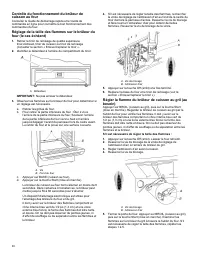
25 4. If the oven bake flame needs to be adjusted, locate the airshutter near the center rear of the drawer cavity behind theaccess panel. Loosen the locking screw and rotate the airshutter until the proper flame appears. Tighten locking screw. A. Locking screwB. Air shutter 5. Push the Off pad when...
Page 26 - SÉCURITÉ DE LA CUISINIÈRE; AVERTISSEMENT
26 SÉCURITÉ DE LA CUISINIÈRE AVERTISSEMENT : Le non-respect à la lettre de ces instructions peut causer un incendie ou une explosion, qui pourrait entraîner des dommages matériels, des blessuresou la mort. − Ne pas remiser de l’essence ou tout autre liquide ou vapeur inflammable à proximité decet ap...
Page 27 - Votre sécurité et celle des autres sont très importantes.
27 AVERTISSEMENT : Les fuites de gaz ne peuvent pas toujours être détectées à l’odorat. Les fournisseurs de gaz recommandent d’utiliser un détecteur de gaz approuvé UL ou CSA. Pour plus d’informations, contacter votre fournisseur de gaz. Si une fuite de gaz est détectée, suivre les instructions de l...
Page 28 - INSTRUCTIONS IMPORTANTES DE SÉCURITÉ; NE JAMAIS; CONSERVER CES INSTRUCTIONS
28 INSTRUCTIONS IMPORTANTES DE SÉCURITÉ AVERTISSEMENT : Afin de réduire le risque d’incendie, de décharge électrique ou de blessures lors de l’utilisation de l’appareil, il convient d’observer certaines précautions fondamentales, notamment : � AVERTISSEMENT : POUR RÉDUIRE LES RISQUES DE BASCULEMENT ...
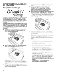
Page 30 - Programme de nettoyage
30 ENTRETIEN ET RÉPARATION DELA CUISINIÈRE Programme de nettoyage La technologie AquaLift ® est une formule de nettoyage innovante qui utilise l’eau et la chaleur pour désincruster les traces derenversements du four en moins d’une heure. Cette nouvelletechnologie de nettoyage à faible niveau de chal...
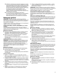
Page 31 - Nettoyage général
31 � Affresh ® Un nettoyant pour appareils ménagers de cuisine et un nettoyant pour table de cuisson affresh ® peuvent être utilisés pour nettoyer le fond du four, ses parois et sa porte lorsque le four a terminé le programme de nettoyage et que sa température est redevenue ambiante. Si l’on utilise...
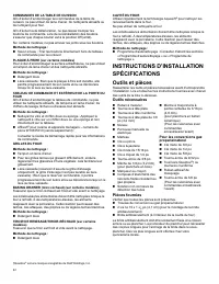
Page 32 - Outils et pièces; Outils nécessaires
32 COMMANDES DE LA TABLE DE CUISSON Afin d’éviter d’endommager les commandes de la table decuisson, ne pas utiliser de laine d’acier, de nettoyants abrasifs oude nettoyant pour four. Afin d’éviter toute détérioration, ne pas laisser tremper lesboutons de commande. Lors de la réinstallation des bouto...
Page 33 - Pièces nécessaires; Exigences d’emplacement
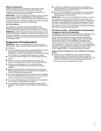
33 Pièces nécessaires Vérifier les codes locaux et consulter le fournisseur de gaz.Vérifier l’alimentation en gaz et l’alimentation électriqueexistantes. Voir les sections « Spécifications électriques » et« Spécifications de l’alimentation en gaz ». IMPORTANT : Lorsque la cuisinière est utilisée sou...
Page 34 - Dimensions de l’armoire
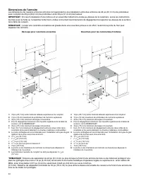
34 Dimensions de l’armoire Les dimensions de l’espace entre les armoires correspondent à une installation entre des armoires de 24 po (61,0 cm) de profondeur,avec comptoir de 25 po (64,0 cm) de profondeur et de 36 po (91,4 cm) de hauteur. IMPORTANT : En cas d’installation d’une hotte ou d’un ensembl...
Page 35 - Spécifications électriques; Type de gaz
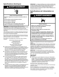
35 Spécifications électriques AVERTISSEMENT Risque de décharge électrique Brancher l’appareil sur une prise à 3 alvéoles reliée à laterre. Ne pas enlever la prise de liaison à la terre. Ne pas utiliser d’adaptateur. Ne pas utiliser de rallonge. Le non-respect de ces instructions peut causer undécès,...
Page 36 - Canalisation d’alimentation en gaz; Détendeur; Déballage de la cuisinière
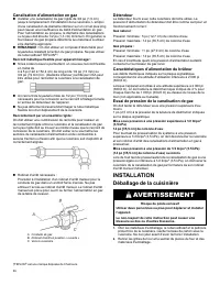
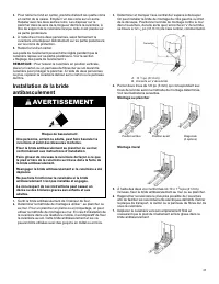
36 Canalisation d’alimentation en gaz � Installer une canalisation de gaz rigide de 3/4 po (1,9 cm) jusqu’à l’emplacement d’installation de la cuisinière. L’emploi d’une canalisation de diamètre inférieur sur un circuit plus long peut causer une insuffisance du débit d’alimentation en gaz. Pour l’al...
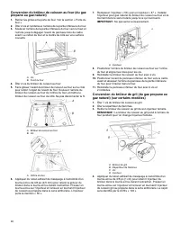
Page 38 - Réglage des pieds de nivellement; Réglage de l’aplomb de la cuisinière; Raccordement au gaz; Raccordement typique par raccord flexible
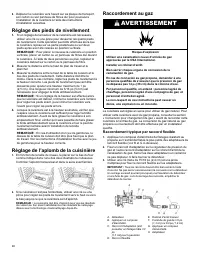
38 8. Déplacer la cuisinière vers l’avant sur sa plaque de transport,son carton ou son panneau de fibres dur pour poursuivrel’installation de la cuisinière à l’aide des instructionsd’installation suivantes. Réglage des pieds de nivellement 1. Si un réglage de la hauteur de la cuisinière est nécessai...
Page 39 - Achever le raccordement
39 Achever le raccordement 1. Vérifier que le robinet d’arrêt du détendeur est à la position« on » (ouvert). A. Robinet d’arrêt du détendeur à la position « on » (ouvert) 2. Ouvrir le robinet d’arrêt manuel sur la canalisationd’alimentation en gaz. Le robinet est ouvert lorsque la manetteest parallè...
Page 40 - Système d’allumage électronique; Allumage initial et réglage des flammes de gaz
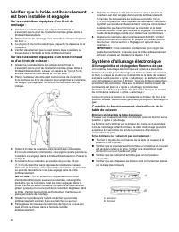
40 Vérifier que la bride antibasculementest bien installée et engagée Sur les cuisinières équipées d’un tiroir deremisage : 1. Glisser la cuisinière dans son emplacement final ens’assurant que le pied de nivellement arrière glisse dans labride antibasculement. 2. Retirer le tiroir de remisage. Voir ...
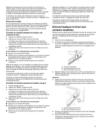
Page 41 - Panne de courant; Contrôle du fonctionnement du brûleur du gril
41 Répéter le processus de mise en marche. Si un brûleur nes’allume pas à ce point, placer les boutons de commande sur« Off » (arrêt) et communiquer avec votre marchand oucompagne de services autorisée pour obtenir de l’aide. Consulterle Guide de démarrage rapide pour obtenir les coordonnées. Si la ...
Page 42 - Porte du four; Achever l’installation
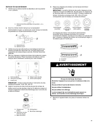
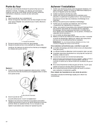
42 Porte du four Il n’est pas recommandé d’enlever la porte du four pour uneutilisation normale. Toutefois, si la dépose est nécessaire,s’assurer que le four est ÉTEINT et froid. Ensuite, suivre lesinstructions ci-dessous. La porte du four est lourde. Retrait : 1. Ouvrir la porte du four complètemen...
Page 46 - Achever l’installation (de gaz naturel à propane)
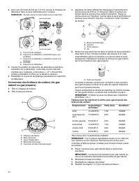
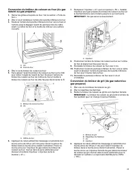
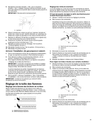
46 5. Remplacer l’injecteur femelle « 155 » par un injecteurfemelle « 100 ». Installer l’injecteur femelle du brûleur du grilpour gaz propane en le tournant dans le sens horaire jusqu’àce qu’il soit serré. IMPORTANT : Ne pas serrer excessivement. A. Injecteur 6. Placer le brûleur de cuisson au gril ...
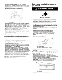
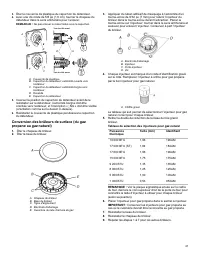
Page 49 - Achever l’installation (de gaz propane à naturel); Réglage de la taille des flammes; Réglage de la flamme des brûleurs de surface; Réglage des brûleurs standard :
49 5. Remplacer l’injecteur femelle « 100 » par un injecteurfemelle « 155 ». Installer l’injecteur femelle du brûleur du grilpour gaz naturel en le tournant dans le sens horaire jusqu’à cequ’il soit serré. IMPORTANT : Ne pas serrer excessivement. A. Injecteur 6. Placer le brûleur de cuisson au gril ...
Page 51 - Déplacement de la cuisinière
51 Déplacement de la cuisinière AVERTISSEMENT Risque de basculement Une personne, enfant ou adulte, peut faire basculer lacuisinière et subir des blessures mortelles. Fixer la bride antibasculement au plancher ou au mur,conformément aux instructions d’installation. Faire glisser de nouveau la cuisin...
Page 52 - NOTES


 JennAir JDRP436HL
User Manual
JennAir JDRP436HL
User Manual
 JennAir JDS1450ML
User Manual
JennAir JDS1450ML
User Manual
 JennAir JDS1750ML
User Manual
JennAir JDS1750ML
User Manual
 JennAir JES1750ML
User Manual
JennAir JES1750ML
User Manual
 JennAir JGRP430HL
User Manual
JennAir JGRP430HL
User Manual
 JennAir JIS1450ML
User Manual
JennAir JIS1450ML
User Manual