Haier HB4200VA1M25, HB4800VA1M25, HB6000VA1M25, HB6000VC1M25 - Manuals
Haier HB4200VA1M25, HB4800VA1M25, HB6000VA1M25, HB6000VC1M25 – Manual in PDF format online.
Manuals:
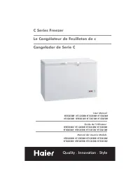
Manual Haier HB4200VA1M25, HB4800VA1M25, HB6000VA1M25, HB6000VC1M25


Summary
INDEX TOPIC PAGE GeneralPhysical dimensionsReplacement Parts SourceInstallation RequirementsAir Flow OrientationHorizontal Left-Hand InstructionsDownflow InstructionsRefrigerant TubingCondensate RemovalElectrical ConnectionsThermostat WiringOrifice ChangeCirculating Air DuctBlower PerformanceStart-u...
D C PRIMARY & SECONDARY CONDENSATE DRAINS- HORIZONTAL 3/4" NPT 2"[5.08 cm] 5.1"[13 cm] 2"[5.08 cm]TYPICAL F K G 1.1"[2.9 cm] 5"[12.7 cm] H 2.4"[ 6 cm] 1.2"[ 3 cm] INLETFRONT VIEW PRIMARY & SECONDARY CONDENSATE DRAINS- UPFLOW 3/4" NPT-FEMALE 1"[2.54cm] ...
AIR FLOW ORIENTATION Downflow discharge(with plastic verticalpan only) (see page 7) *Horizontal Right Discharge Tube and Drain conn. front Horizontal Left DischargeTube and Drain conn. front(see page 6) Important:Remove the horizontal pan whenunit is installed in unconditionedi.e. (Garage, Attic ) a...
Haier Manuals
-
 Haier HF11CM10NW
User Manual
Haier HF11CM10NW
User Manual
-
Haier HF11CM10NW
Manual
-
 Haier BCF46B
User Manual
Haier BCF46B
User Manual
-
 Haier HCC2230AGS
User Manual
Haier HCC2230AGS
User Manual
-
Haier HCC2230AGS
Installation Manual
-
 Haier HLTD500ACW
User Manual
Haier HLTD500ACW
User Manual
-
 Haier HRT18RCPB1
User Manual
Haier HRT18RCPB1
User Manual
-
 Haier HVTS18DTBB
User Manual
Haier HVTS18DTBB
User Manual
-
Haier HRT18RCWB1
User Manual
-
 Haier HRT18R1APB
User Manual
Haier HRT18R1APB
User Manual
-
 Haier ESA3159
User Manual
Haier ESA3159
User Manual
-
 Haier CPN11XCJ
User Manual
Haier CPN11XCJ
User Manual
-
Haier HLTD500AEW
User Manual
-
 Haier PBFS21EDAS
User Manual
Haier PBFS21EDAS
User Manual
-
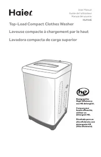 Haier HLP24E
User Manual
Haier HLP24E
User Manual
-
 Haier DWL4035DBWW
User Manual
Haier DWL4035DBWW
User Manual
-
Haier ESA3189
User Manual
-
 Haier CPN12XH9
User Manual
Haier CPN12XH9
User Manual
-
Haier CPN10XCJ
User Manual
-
Haier PBFS21EDBP
User Manual