Gasmate GM160-018 - Manuals
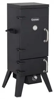
User Manual Gasmate GM160-018


Summary
2 3 GENERAL INFORMATION Gas Installation Codes • Smokers must be used in accordance with AS/NZS Standard 5601 “Gas Installations”. • Smokers for use with bottled gas are labelled LPG/ULPG.• Smokers for use with natural gas are labelled ‘natural gas’ and must be installed by an authorised person. Che...
4 5 • DO NOT wear loose clothing while operating the smoker. Tie back long hair while operating the smoker. ALWAYS wear fully-covering shoes while operating the smoker. • Allow the smoker and its components to cool completely before conducting any routine cleaning or maintenance. • NEVER use glasswa...
6 7 ASSEMBLY INSTRUCTIONS Before assembling the smoker, read these Instructions carefully. Assemble the smoker on a flat, clean surface. The smoker is heavy. NOTE: Do not fully tighten all the nuts during the initial stages of assembly. Caution: Sheet metal can cause injury. Wear gloves when assembl...
Gasmate BBQs Manuals
-
 Gasmate BQ1051
User Manual
Gasmate BQ1051
User Manual
-
 Gasmate BQ1056
User Manual
Gasmate BQ1056
User Manual
-
 Gasmate BQ1070F
User Manual
Gasmate BQ1070F
User Manual
-
 Gasmate BQ1071F
User Manual
Gasmate BQ1071F
User Manual
-
 Gasmate BQ1077
User Manual
Gasmate BQ1077
User Manual
-
 Gasmate BQ1078
User Manual
Gasmate BQ1078
User Manual
-
 Gasmate BQ1084
User Manual
Gasmate BQ1084
User Manual
-
 Gasmate BQ1085
User Manual
Gasmate BQ1085
User Manual
-
 Gasmate BQ1090B
User Manual
Gasmate BQ1090B
User Manual
-
 Gasmate BQ1090BNG
User Manual
Gasmate BQ1090BNG
User Manual
-
 Gasmate BQ1096
User Manual
Gasmate BQ1096
User Manual
-
 Gasmate BQ1096NG
User Manual
Gasmate BQ1096NG
User Manual
-
 Gasmate BQ1190BLB
User Manual
Gasmate BQ1190BLB
User Manual
-
 Gasmate BQ1190BLBNG
User Manual
Gasmate BQ1190BLBNG
User Manual
-
 Gasmate CS6095
User Manual
Gasmate CS6095
User Manual