Electrolux ERCE9025SA - Manuals
User Manual Electrolux ERCE9025SA


Summary
2 CONTENTS 3 Important safety instructions 4 Product description 5 Dimensions 6 Rangehood installation 9 Using the rangehood 9 Maintenance and cleaning 9 Changing the halogen lamps 10 Optional ducting accessories 11 Warranty LEGEND The symbols you will see in this booklet have these meanings: WARNIN...
3 Electrical connection Check that the mains voltage matches with the voltage on the data plate inside the rangehood. Check that the installation complies with standards of local building, gas and electrical authorities. Before connecting to the mains supply ensure that the mains voltage corresponds...
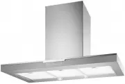
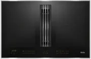
4 PRODUCT DESCRIPTION Additional items required for installation • Fixings required to attach rangehood body and anti-tilt points. • Fixings required to attach flue cover mounting brackets to the wall. • Duct tape or cable ties. Technical specification Power supply: 220-240 Volts 50Hz. Connects to 7...
Electrolux Range Hoods Manuals
-
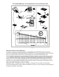 Electrolux Collo150
User Manual
Electrolux Collo150
User Manual
-
 Electrolux EFC226B
User Manual
Electrolux EFC226B
User Manual
-
 Electrolux EFC226C
User Manual
Electrolux EFC226C
User Manual
-
 Electrolux EFC226R
User Manual
Electrolux EFC226R
User Manual
-
 Electrolux EFC226V
User Manual
Electrolux EFC226V
User Manual
-
 Electrolux EFC60441OC
User Manual
Electrolux EFC60441OC
User Manual
-
 Electrolux EFC60441OR
User Manual
Electrolux EFC60441OR
User Manual
-
 Electrolux EFC60441OV
User Manual
Electrolux EFC60441OV
User Manual
-
 Electrolux EFG50250S
User Manual
Electrolux EFG50250S
User Manual
-
 Electrolux EFP6500XA
User Manual
Electrolux EFP6500XA
User Manual
-
 Electrolux EFP9500XA
User Manual
Electrolux EFP9500XA
User Manual
-
 Electrolux EFU9216W
User Manual
Electrolux EFU9216W
User Manual
-
 Electrolux EFV516K
User Manual
Electrolux EFV516K
User Manual
-
 Electrolux EFV516W
User Manual
Electrolux EFV516W
User Manual
-
 Electrolux ERC925DSD
User Manual
Electrolux ERC925DSD
User Manual
-
 Electrolux ERC926BA
User Manual
Electrolux ERC926BA
User Manual
-
 Electrolux ERC928GA
User Manual
Electrolux ERC928GA
User Manual
-
 Electrolux ERC930SA
User Manual
Electrolux ERC930SA
User Manual
-
 Electrolux ERCE9025BA
User Manual
Electrolux ERCE9025BA
User Manual
-
 Electrolux ERCE9025BK
User Manual
Electrolux ERCE9025BK
User Manual