Page 2 - Special symbols
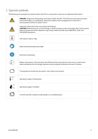
614-40094-00 2 1 Special symbols The following are examples of symbols used on the UPS or accessories to alert you to important information: DANGER: Dangerous voltage levels are present within the UPS. The UPS has its own internal power source (the battery). Consequently, the power outlets may be en...
Page 3 - Table of content
614-40094-00 3 2 Table of content 1 Special symbols ........................................................................................................... 2 2 Table of content ........................................................................................................... 3 3 Intro...
Page 5 - Introduction; Environmental protection; Substances; End of life
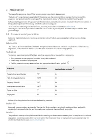
614-40094-00 5 •• • Materials Abbreviations Number in the symbols Polyethylene terephthalate PET 01 High-density polyethylene HDPE 02 Polyvinyl chloride PVC 03 Low-density polyethylene LDPE 04 Polypropylene PP 05 Polystyrene PS 06 3 Introduction Thank you for selecting an Eaton 5PX product to protec...
Page 6 - Battery
614-40094-00 6 Battery The product contains lead-acid batteries that must be processed according to applicable local regulations concerning batteries. The battery may be removed to comply with regulations and in view of correct disposal. 3.2 Benefits The Eaton 5PX uninterruptible power system (UPS)...
Page 7 - Presentation; Standard installation; Weights and dimensions
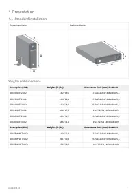
614-40094-00 7 4 Presentation 4.1 Standard installation Tower installation Rack installation Weights and dimensions Description (UPS) Weights (lb / kg) Dimentions (inch / mm) D x W x H 5PX1000IRT2UG2 43.2 / 19,6 17.6x17.2x3.4 / 448x438x85,5 5PX1500IRT2UG2 49.4 / 22,4 17.6x17.2x3.4 / 448x438x85,5 5PX...
Page 9 - Optional accessories; Installation; Inspecting the equipment
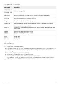
614-40094-00 9 1.2. 4.3 Optional accessories Part number Description 5PXEBM48RT2UG25PXEBM72RT2UG25PXEBM72RT3UG2 Extended Battery Module Network-M2 Eaton Gigabit Network Card (SNMP v1/v3 and IP v4/v6 // Ethernet 10/100/1000BaseT) INDGW-M2 Eaton Industrial Gateway Card (Modbus TCP / RTU) Relay-MS Eato...
Page 10 - Package content
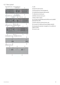
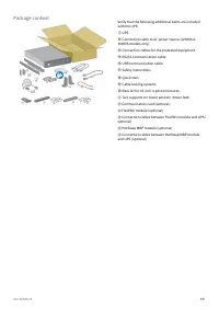
614-40094-00 10 Package content Verify that the following additional items are included with the UPS: ① UPS ⑬ Connection cable to AC power source (2200VA & 3000VA models only) ⑭ Connection cables for the protected equipment ⑮ RS232 communication cable ⑯ USB communication cable ⑰ Safety instru...
Page 11 - Recommended positions; Installation in tower position
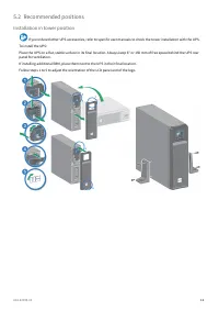
614-40094-00 11 5.2 Recommended positions Installation in tower position If you ordered other UPS accessories, refer to specific user manuals to check the tower installation with the UPS. To install the UPS: Place the UPS on a flat, stable surface in its final location. Always keep 6" or 150 mm ...
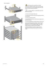
Page 12 - Installation in rack position
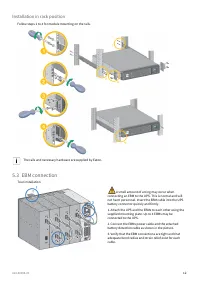
614-40094-00 12 Installation in rack position Follow steps 1 to 4 for module mounting on the rails. The rails and necessary hardware are supplied by Eaton. 5.3 EBM connection Tour installation A small amount of arcing may occur when connecting an EBM to the UPS. This is normal and will not harm pers...
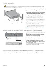
Page 15 - HotSwap MBP module operation
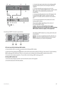
614-40094-00 15 1. Connect the input socket (48) on the HotSwap MBP module to the AC power source using the cable (13) supplied. 2. Connect the UPS input socket (2) to the “UPS Input” (47) on the HotSwap MBP module, using the cable (26) supplied. This cable and the connector are marked blue. 3. C...
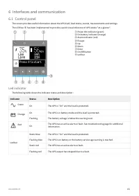
Page 16 - Interfaces and communication; Led indicator
614-40094-00 16 6 Interfaces and communication 6.1 Control panel The screen provides useful information about the UPS itself, load status, events, measurements and settings. The LED bar ⑨ has been implemented to provide a quick visual reference of UPS status "at-a-glance". ① Power ON indicat...
Page 18 - Display functions; Menu map for display functions
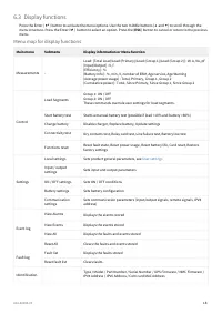
614-40094-00 18 6.3 Display functions Press the Enter ( ⮠ ) button to activate the menu options. Use the two middle buttons ( ⯅ and ⯆ ) to scroll through the menu structure. Press the Enter ( ⮠ ) button to select an option. Press the ( ESC ) button to cancel or return to the previous menu. Me...
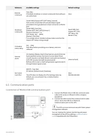
Page 23 - Communication ports; Connection of RS232/USB communication port
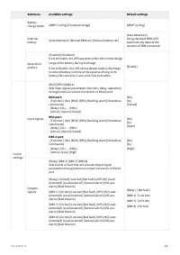
614-40094-00 23 1. 2. Submenu Available settings Default settings Remote command [Yes] [No]If Enabled, shutdown or restart commands from software are authorized. [Yes] Shutdown commands [Send CMD] [Output OFF] [OFF delay] [restart]Sets events or fault that will actuate Output signal parameters throu...
Page 25 - UPS remote control functions; Connectivity cards; Programmable signal inputs
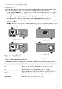
614-40094-00 25 • • • • 6.6 UPS remote control functions Connectivity cards Connectivity cards allow the UPS to communicate in a variety of networking environments and with different types of devices. The 5PX models have one available communication bay for the following connectivity cards: Gigabit N...
Page 27 - Programmable signal outputs
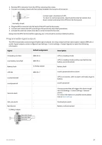
614-40094-00 27 2.3. 4.5.6. Remove RPO connector from the UPS by removing the screws.Connect a normally closed volt-free contact between the two pins of connector. Normally closed Contact open: shut down of UPS. To return to normal operation, deactivate the external remote shut down contact and res...
Page 28 - Eaton Intelligent Power Software suite; Operation; Battery charge; Starting the UPS on battery
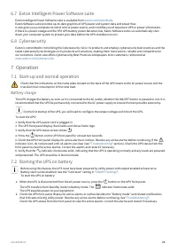
614-40094-00 28 1. 2. 6.7 Eaton Intelligent Power Software suite Eaton Intelligent Power Software suite is available from eaton.com/downloads . Eaton Software suite provides up-to-date graphics of UPS power and system data and power flow. It also gives you a complete record of critical power events,...
Page 29 - Normal mode; Return of AC input power
614-40094-00 29 •• ••• 7.3 UPS shutdown To shut down the UPS: Press the button on the front panel for three seconds. A confirmation message will appear. When confirmed, the UPS starts to beep and shows a status of "UPS shutting OFF...". The UPS then transfers to Standby mode, and the ind...
Page 30 - Retrieving the event log; Retrieving the fault log; UPS maintenance; Storing the equipment
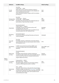
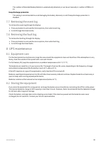
614-40094-00 30 1.2. 1.2. The number of Extended Battery Module is automatically detected, or can be set manually in number of EBM or in Ah. Deep discharge protection This setting is recommended to avoid damaging the battery. Warranty is void if deep discharge protection is disabled. 7.7 Retrieving ...
Page 31 - When to replace batteries; Replacing batteries
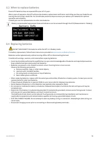
614-40094-00 31 • • a. b. c. d. • ••• • • • 8.3 When to replace batteries Eaton UPS batteries have an expected life span of 3-5 years. After 4 years of operation, the UPS will provide a battery replacement notification reminding you that your batteries are nearing the end of their useful life. You s...
Page 32 - Replacing the internal battery :
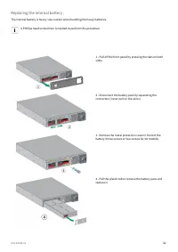
614-40094-00 32 Replacing the internal battery : The internal battery is heavy. Use caution when handling the heavy batteries. A Phillips head screwdriver is needed to perform this procedure 1 - Pull off the front panel by pressing the tabs on both sides. 2 - Disconnect the battery pack by separa...
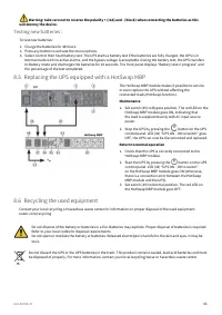
Page 33 - Testing new batteries :; Replacing the UPS equipped with a HotSwap MBP; Recycling the used equipment
614-40094-00 33 1.2.3. 1. 2. 1. 2. 3. Warning: take care not to reverse the polarity + (red) and - (black) when connecting the batteries as this will destroy the device. Testing new batteries : To test new batteries: Charge the batteries for 48 hours.Press any button to activate the menu options.Sel...
Page 34 - Troubleshooting; Typical alarms and faults
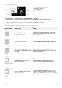
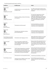
614-40094-00 34 •• • 1.2.3. Do not discard waste electrical or electronic equipment (WEEE) in the trash. For proper disposal, contact your local recycling/reuse or hazardous waste center. 9 Troubleshooting The Eaton 5PX is designed for reliable, autonomous operation while providing you with notifica...
Page 36 - 0 Specification and technical characteristics
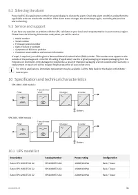
614-40094-00 36 •••••• 9.2 Silencing the alarm Press the ESC (Escape) button on the front panel display to silence the alarm. Check the alarm condition and perform the applicable action to resolve the condition. If the alarm status changes, the alarm beeps again, overriding the previous alarm silenc...
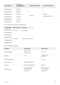
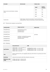
Page 39 - Electrical output connection
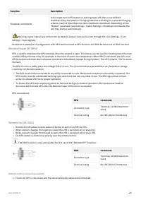
614-40094-00 39 All models Normal mode Battery mode Short circuit current limitation in b attery mode Model Current limitation 1000 31A 1500 38A 2200 38A 3000 64A Transfer time Utility Outage: 1-4ms for normal mode, >5ms for sensitive mode Utility abnormal: <10ms for normal mode ,<25ms for...
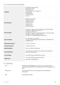
Page 40 - Environmental and safety
614-40094-00 40 10.9 Environmental and safety Standards IEC/EN 62040-1:2008+A1:2013EN IEC 62040-2: 2018 IEC 62040-2: 2016 FCC CFR Title 47, Part 15, Subpart BIEC/EN 62040-3IEC 62040-1:2017UL1778 5th editionCSA 22.2 EMC (Emissions) EN IEC 62040-2: 2018 C1EN 62040-2: 2006 C1IEC 62040-2: 2016 C1EN 5501...