Page 2 - WARNING –
IMPORTANT THESE INSTRUCTIONS SHOULD BE READ CAREFULLY AND RETAINED FOR FUTURE REFERENCE. Note also the information presented on the appliance CAUTION: FAILURE TO FOLLOW THESE INSTRUCTIONS MAY CAUSE INJURY AND/OR DAMAGE AND MAY INVALIDATE YOUR WARRANTY Please read the operating instructions carefully...
Page 10 - Specification
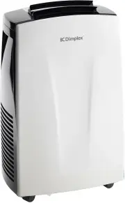
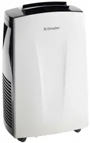
Model no. DCP7W Colour White Power supply 220-240V~, 50Hz Operating temperature 17-35°C Thermostat range 17-30°C Rated Input Power 0.98kW Cooling Capacity 1.93kW Dehumidification Capacity 1.93L/hour Noise Level Minimum (Lo) 51dB(A) Noise Level Maximum (Hi) 62dB(A) Air Volume (Lo/Hi) 211/272 Refriger...
Page 11 - Parts
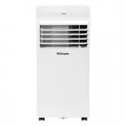
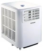
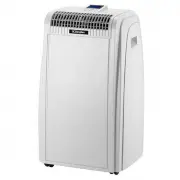
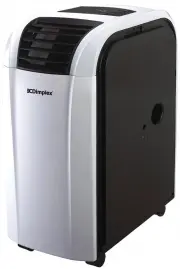
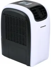
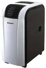
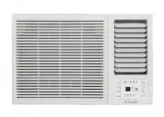
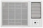
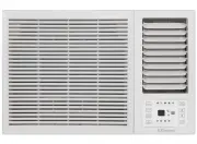
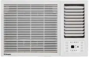
Parts (1) Control panel (2) Remote signal receptor (3) Horizontal manual louvre control lever (4) Vertical manual louvre control lever (5) Panel(6) Caster (7) Handle (both sides)(8) Air filter(9) Upper air intake(10) Drain outlet(11) Air outlet(12) Lower air intake(13) Bottom tray drain outlet (1) (...
Page 12 - Control Panel; Mode button; Switches power on or off.
Control Panel (1) Mode button (2) Temp decrease (-) button (3) Indicator light (4) LED display screen (5) Temp increase (+) button (6) Power button FRESH( Press 3s ) (1) (2) (3) (4) (5) (6) Mode button: Selects the appropriate operating mode. Each time you press the button, a mode is selected in a s...
Page 13 - USING THE REMOTE CONTROL
LED Display Shows the set temperature while on Cool, Heat or Auto mode (on some models). While on Dry and Fan modes, it shows the room temperature. Error codes: E0 - EEPROM error.E1 - Room temperature sensor error.E2 - Evaporator temperature sensor error.E3 - Condenser temperature sensor error (on s...
Page 14 - Remote Control; HIGH; AUTO; Mode display
Remote Control Note: All indicators shown in the figure are for the purpose of clear presentation. But during the actaul operation, only the relative function signs are shown on the display window. Displayed when data transmitted. Displayed when remote controller is ON. NO display High speed Medium ...
Page 15 - Installation; EXHAUST HOSE INSTALLATION; as this could cause damage to the unit.; RECOMMENDED INSTALLATION
Installation EXHAUST HOSE INSTALLATION The exhaust hose and adaptor must be installed or removed in accordance with the usage mode. For COOL, HEAT (heat pump type) or AUTO (on some models) mode the exhaust hose must be installed. For FAN, DRY or HEAT (electrical heat type) the exhaust hose should be...
Page 16 - WINDOW KIT INSTALLATION; Preparing the exhaust hose assembly; Type window installation:
Installation WINDOW KIT INSTALLATION The window slider kit has been designed to fit most standard vertical and horizontal window applications, however it may be necessary for you to modify some aspects of the installation procedures for certain types of windows. Step one: Preparing the exhaust hose ...
Page 17 - Install the exhaust hose assembly to the unit
Installation WINDOW KIT INSTALLATION Step two: Install the exhaust hose assembly to the unit Push the Exhaust hose into the air outlet opening of the unit along the arrow direction. Step three: Preparing the adjustable window slider 1. Choose the window sliders according the size of your window. If ...
Page 19 - choose from one of the following two installation methods.
Installation WINDOW KIT INSTALLATION Note: Once the exhaust hose assembly and adjustable window lider are prepared, choose from one of the following two installation methods. Type 1: Hung Window or Sliding Window Installation (for some models) Or and frame as shown. 1. Cut the adhesive foam seal A a...
Page 20 - min; NOTE: Cover the hole using the; Wall Exhaust
Installation Type 2: Wall Installation (for some models)1. Cut a 125mm (4.9inch) hole into the wall for wall exhaust adaptor B.2. Secure the wall exhaust adaptor B to the wall using the four anchors and screws provided in the kit.3. Connect the exhaust hose assembly (with wall exhaust adaptor A) to ...
Page 21 - TOOLS NEEDED
Installation TOOLS NEEDED • Medium Philips screwdriver• Tape measure or ruler• Knife or scissors• Saw (optional, to shorten window kit for narrow windows ACCESSORIES (not all accessories supplied with all models) Nam e Qty. of Acce ssories Shape Shape Qty. Nam e of Acce ssories 1 pc(*) Window Slider...
Page 22 - Operating Instructions; COOL operation
Operating Instructions COOL operation · Press the "MODE" button until the "COOL" indicator light comes on.· Press the ADJUST buttons "+" or "-" to select your desired room temperature. The temperature can be set within a range of 17°C~30°C/62°F~88°F(or 86°F).· Press t...
Page 23 - AIR FLOW DIRECTION ADJUSTMENT
Operating Instructions Constant Fan button (On some models) In Cooling or Dry mode, press the button for 3 seconds to turn on or off the constant fanfunction. When the function is turned on, the constant fan light will illuminate, identifyingthe fan continuous run for cooling. When the function is t...
Page 24 - WATER DRAINAGE; POWER MANAGEMENT feature (On some models); Water Drainage; Continuous
WATER DRAINAGE · During dehumidifying modes, remove the drain plug from the back of the unit, install the drain connector (5/8" universal female mender) with 3/4" hose (purchased separately). For the models without drain connector, just attach the drain hose to the hole. Place the open end o...
Page 26 - Cleaning; SAFETY PRECAUTIONS; Never operate the unit without a filter in place.; Outside Cabinet; for any stubborn marks.; IMPORTANT
Cleaning SAFETY PRECAUTIONS • Always unplug the unit before cleaning or servicing.• DO NOT use flammable liquids or chemicals to clean the unit.• DO NOT wash the unit under running water. Doing so causes electrical danger.• DO NOT operate the machine if the power supply was damaged during cleaning. A...
Page 27 - Storage; Maintenance; Warranty
Storage If not using the unit for an extended period of time, after cleaning please:• Turn the unit OFF, unplug and take care of the mains lead & plug.• Drain any water from the unit according to the instructions in the following sections.• Run the appliance on FAN MODE for 12 hours in a warm ro...