Page 2 - Safety; Important safety instructions – Save these instructions
2 Safety Important safety instructions – Save these instructions There exists dangerous voltage and high temperature inside the UPS. During the installation, operation and maintenance, please abide the local safety instructions and relative laws, otherwise it will result in personnel injury or equip...
Page 3 - Symbols used in this guide; Product Introduction; UPS Module Outlook
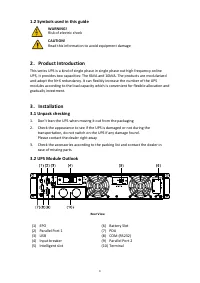
3 1.2 Symbols used in this guide WARNING! Risk of electric shock CAUTION! Read this information to avoid equipment damage 2 . Product Introduction This series UPS is a kind of single phase in single phase out high frequency online UPS, it provides two capacities: The 6kVA and 10kVA. The products are...
Page 4 - LCD control panel; button; Installation notes; If the environment temperature exceeds 40
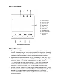
4 3.3 LCD control panel LCD control panel introduction (1) INVERTER LED (2) BATTERY LED (3) BYPASS LED (4) ALARM LED (5) LCD display (6) UP button (7) DOWN button (8) ESC /OFF button (9) ENTER/ON button 3.4 Installation notes Please place the UPS in a clean, stable environment, avoid the vibration...
Page 5 - External Protective Devices; External Battery
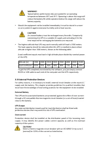
5 WARNING! Typical battery performance data are quoted for an operating temperature between 20°C and 25°C. Operating it above this range will reduce the battery life while operation below this range will reduce the battery capacity. Should the equipment not be installed immediately it must be stor...
Page 6 - Power cable connect
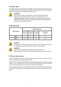
6 3.6 Power Cables The cable design shall comply with the voltages and currents provided in this section, Kindly follow local wiring practices and take into consideration the environmental conditions (temperature and physical support media). WARNING! Upon starting, please ensure that you are aware o...
Page 7 - safely isolated at their ends.; Battery connection; of the 8
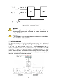
7 Input connection “single phase + ground” WARNING! If the load equipment is not ready to accept power on the arrival of the commissioning engineer then ensure that the system output cables are safely isolated at their ends. CAUTION! The earthing and neutral bonding arrangement must be in accordance...
Page 8 - Note; Operation
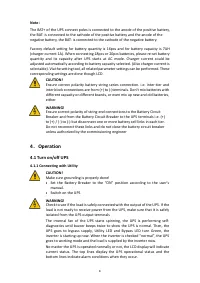
8 Note : The BAT+ of the UPS connect poles is connected to the anode of the positive battery, the BAT- is connected to the cathode of the positive battery and the anode of the negative battery, the BAT- is connected to the cathode of the negative battery. Factory default setting for battery quantity...
Page 9 - Disconnecting with Utility; LCD Display instruction
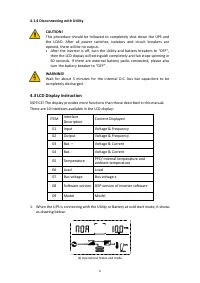
9 4.1.4 Disconnecting with Utility CAUTION! This procedure should be followed to completely shut down the UPS and the LOAD. After all power switches, isolators and circuit breakers are opened, there will be no output. • After the inverter is off, turn the Utility and battery breakers to “OFF”, then ...
Page 10 - the corresponding user manual.
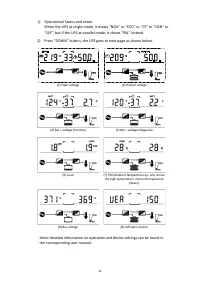
10 1) Operational Status and mode When the UPS at single mode, it shows “NOA” or “ECO” or “CF” or “GEN” or “SEF”, but If the UPS at parallel mode, it shows “PAL” instead 2) Press “DOWN” button, the UPS goes to next page as shown below. (2) Input voltage (3) Output voltage (4) Bat + voltage (Positive...