Page 2 - Table of Contents
2 Table of Contents 1. Important Safety Warning ....................................................................................... 3 1.1 Transportation .................................................................................................... 3 1.2 Preparation............................
Page 3 - Important safety warning; Important safety instructions – Save these instructions
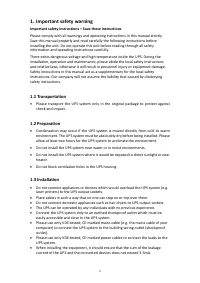
3 1. Important safety warning Important safety instructions – Save these instructions Please comply with all warnings and operating instructions in this manual strictly. Save this manual properly and read carefully the following instructions before installing the unit. Do not operate this unit befor...
Page 5 - Symbols used in this guide; Installation and setup
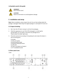
5 1.6 Symbols used in this guide WARNING! Risk of electric shock CAUTION! Read this information to avoid equipment damage 2. Installation and setup Note: Before installation, please inspect the unit. Be sure that nothing inside the package is damaged. Please keep the original package in a safe place...
Page 7 - Installing the UPS; Rackmount installation
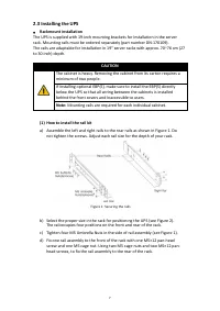
7 2.3 Installing the UPS • Rackmount installation The UPS is supplied with 19-inch mounting brackets for installation in the server rack. Mounting rails must be ordered separately (part number DN-170109). The rails are adaptable for installation in 19" server racks with approx. 70~76 cm (27 to 3...
Page 8 - Repeat Steps 3 and 4 for the other rail assembly.; Slide the UPS and any other optional cabinets into the rack.
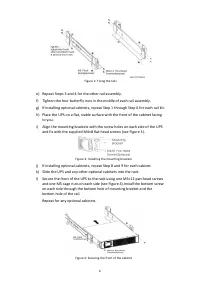
8 Figure 2: Fixing the rails e) Repeat Steps 3 and 4 for the other rail assembly. f) Tighten the four butterfly nuts in the middle of each rail assembly. g) If installing optional cabinets, repeat Step 1 through Step 6 for each rail kit. h) Place the UPS on a flat, stable surface with the front of t...
Page 9 - Rackmount wiring installation; Do not make unauthorized changes to the ups otherwise, damage may; CAUTION; A small amount of arcing may occur when connecting the internal
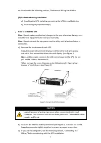
9 m) Continue to the following section, “Rackmount Wiring Installation. (2) Rackmount wiring installation a) Installing the UPS, including connecting the UPS internal batteries b) Connecting any Optional EBP(S) • How to install the UPS Note: Do not make unauthorized changes to the ups; otherwise, da...
Page 11 - To install the optional EBP(s) for a UPS; For the bottom (or only) EBP, remove the EBP cable knockout on the top; A small amount of arcing may occur when connecting an EBP to the UPS.
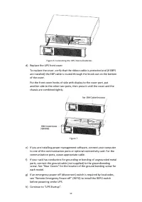
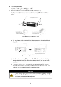
11 • Connecting the EBP(s) (1) To install the optional EBP(s) for a UPS a) Remove the front cover of each EBP and UPS (see Figure 8). It is the same with the installation of the front cover. (Refer” To install the UPS“) Figure 8: Removing the EBP Front Cover b) On the bottom of the UPS front cover, ...
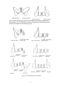
Page 12 - Rackmount converted to tower plasticbase installation
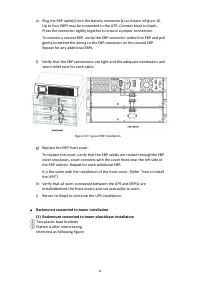
12 e) Plug the EBP cable(s) into the battery connector(s) as shown inFigure 10. Up to four EBPS may be connected to the UPS. Connect black to black,. Press the connector tightly together to ensure a proper connection. To connect a second EBP, unclip the EBP connector onthe first EBP and pull gently ...
Page 14 - The installation between UPS and EBPS can be referred to Figure 14
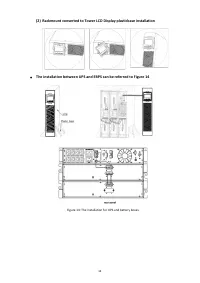
14 (2) Rackmount converted to Tower LCD Display plasticbase installation • The installation between UPS and EBPS can be referred to Figure 14 Figure 14: The installation for UPS and battery boxes
Page 15 - UPS startup and turn off; Startup operation
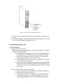
15 Figure 15: Long backup external battery connection a) Install the base, then place the RT UPS on the base one by one as Figure 13 shows. b) The cover installation and cable connection of the UPS and EBPS are the same as RT. (To install the optional EBP(s) for a UPS) 2.4 UPS startup and turn off •...
Page 16 - Turn off operation; Configuring battery settings; Set the UPS for the number of EBPs installed; Operation and display panel
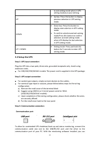
16 • Turn off operation (1) Turn off the UPS in line mode a) Press and hold the OFF key for more than half a second to turn off the UPS and inverter. b) After the UPS shutdown, the LEDs go out and there is no output. If output is needed, you can set bps “ON” onthe LCD setting menu. (2) Turn off the ...
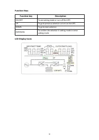
Page 17 - Function keys; LED indicator
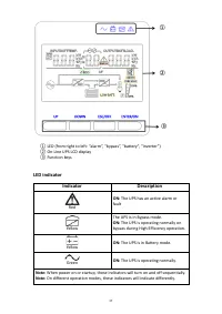
17 ① LED (from right to left: “alarm”, “bypass”, “battery”, “inverter”) ② On -Line UPS LCD display ③ Function keys LED indicator Indicator Description Red ON: The UPS has an active alarm or fault Yellow The UPS is in Bypass mode. ON: The UPS is operating normally on bypass during High Efficiency ope...
Page 19 - Input source information
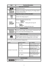
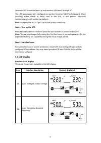
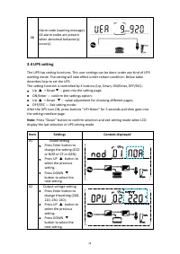
19 Icon Function/Description Input source information Indicates the AC input Indicates input voltage, input frequency, PV voltage, battery voltage and temperature Configuration program and fault information Indicates the settings programs Indicates the warning and fault codes Warning: flashing with ...
Page 20 - Operations; Button operation
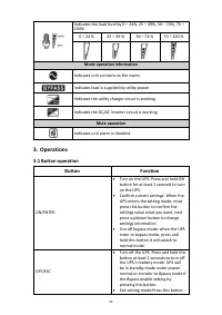
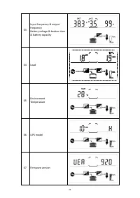
20 Indicates the load level by 0 – 24%, 25 – 49%, 50 – 74%, 75 – 100% 0 – 24 % 25 – 49 % 50 – 74 % 75 – 100 % Mode operation information Indicates unit connects to the mains Indicates load is supplied by utility power Indicates the utility charger circuit is working Indicates the DC/AC inverter circ...
Page 27 - Alarm or fault reference code
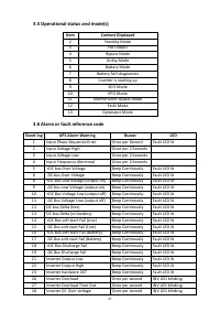
27 3.5 Operational status and mode(s) Item Content Displayed 2 Standby Mode 3 No Output 4 Bypass Mode 5 Utility Mode 6 Battery Mode 7 Battery Self-diagnostics 8 Inverter is starting up 9 ECO Mode 10 EPO Mode 11 Maintenance Bypass Mode 12 Fault Mode 13 Generator Mode 3.6 Alarm or fault reference code...
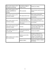
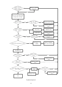
Page 28 - Troubleshooting; Symptom
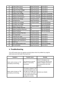
28 32 Output Short Circuit Beep Continously Fault LED lit 33 Output Over Voltage Beep Continously Fault LED lit 34 Output Svr Over Voltage Beep Continously Fault LED lit 35 Output Low Voltage Beep Continously Fault LED lit 39 +Battery Over Voltage Once per second BATTERY LED blinking 41 +Battery Dis...
Page 33 - EPO function is not needed.; Load Segments
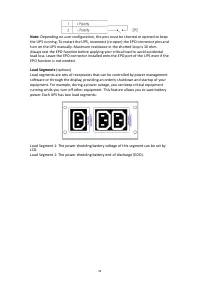
33 Note: Depending on user configuration, the pins must be shorted or opened to keep the UPS running. To restart the UPS, reconnect (re-open) the EPO connector pins and turn on the UPS manually. Maximum resistance in the shorted loop is 10 ohm. Always test the EPO function before applying your criti...
Page 34 - Specification; MODEL
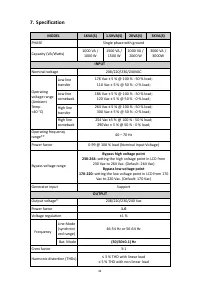
34 7. Specification MODEL 1KVA(S) 1.5KVA(S) 2KVA(S) 3KVA(S) PHASE Single phase with ground Capacity (VA/Watts) 1000 VA / 1000 W 1500 VA / 1500 W 2000 VA / 2000 W 3000 VA / 3000W INPUT Nominal voltage 208/220/230/240VAC Operating voltage range (Ambient Temp. <40 °C) Low line transfer 176 Vac ± 5 %...
Page 36 - PHYSICAL; Safety
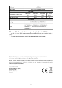
36 Altitude < 1500m Noise level Less than 55dBA at 1 Meter PHYSICAL Dimension W×D×H (mm) 440*325* 86.5 440*460* 86.5 440*460* 86.5 440*600* 86.5 Net Weight (kg) 11.3 15.5 19.5 26 STANDARDS Safety IEC/EN62040-1,IEC/EN60950-1 EMC IEC/EN62040-2, IEC61000-4-2, IEC61000-4-3, IEC61000-4-4, IEC61000-4-5...