DeLonghi DEGLSC 24 SS - Manuals
DeLonghi DEGLSC 24 SS – Manual in PDF format online.
Manuals:
Manual DeLonghi DEGLSC 24 SS


Summary
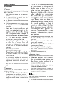
2 WARNING • ALL RANGES CAN TIP • INJURY TO PERSON COULD RESULT • INSTALL ANTI-TIP DEVICE PACKED WITH RANGE • SEE INSTALLATION INSTRUCTIONS This appliance is designed and manufactured solely for the cooking of domestic (household)food and in not suitable for any none domestic application and therefor...
3 WARNING! THIS APPLIANCE HAS TO BE INSTALLED BY A QUALIFIED INSTALLER. Installation must conform with local codes. Improper installation, adjustment, alteration, services, or maintenance can cause injury or property damage. Consult aqualified installer or a service agent. IMPORTANT: The use of suit...
4 WARNING!! ELECTRICAL GROUNDING INSTRUCTIONS The range must be electrically grounded in accordancewith local codes or, in the absence of local codes, with theNational Electrical Code, ANSI/NFPA No. 70-latest edition.Installation should be made by a Iicensed electrician. FOR PERSONAL SAFETY, THIS AP...
DeLonghi Manuals
-
 DeLonghi EN640 B
User Manual
DeLonghi EN640 B
User Manual
-
 DeLonghi EN640 W
User Manual
DeLonghi EN640 W
User Manual
-
 DeLonghi ENV95
User Manual
DeLonghi ENV95
User Manual
-
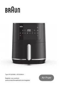 DeLonghi HF3030IBK
User Manual
DeLonghi HF3030IBK
User Manual
-
 DeLonghi EXAM440 55 B
Manual
DeLonghi EXAM440 55 B
Manual
-
 DeLonghi KG210
User Manual
DeLonghi KG210
User Manual
-
DeLonghi KG210
Manual
-
 DeLonghi CGH1112DP
User Manual
DeLonghi CGH1112DP
User Manual
-
 DeLonghi NSM 11 XL
User Manual
DeLonghi NSM 11 XL
User Manual
-
DeLonghi NSM 7 NL
User Manual
-
 DeLonghi ENV90
Manual
DeLonghi ENV90
Manual
-
DeLonghi ENV90
User Manual
-
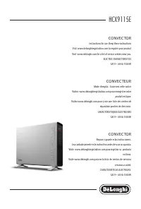 DeLonghi HCX9115E
User Manual
DeLonghi HCX9115E
User Manual
-
DeLonghi HCX9115E
Manual
-
DeLonghi HCX9115E
Installation Manual
-
 DeLonghi HFX60O15L
Manual
DeLonghi HFX60O15L
Manual
-
 DeLonghi TRLS0715EL
Manual
DeLonghi TRLS0715EL
Manual
-
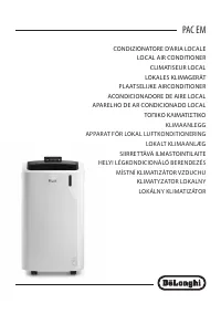 DeLonghi PAC EM93
User Manual
DeLonghi PAC EM93
User Manual
-
 DeLonghi EC230 BK
Manual
DeLonghi EC230 BK
Manual
-
DeLonghi EC230 BK
User Manual