Best UCB3I30SBW - Manuals
Best UCB3I30SBW Range Hood – User Manual in PDF format online.
Manuals:
User Manual Best UCB3I30SBW


Summary
2 TO REDUCE THE RISK OF FIRE, ELECTRIC SHOCK OR INJURY TO PERSONS, OBSERVE THE FOLLOWING: 1. Use this unit only in the manner intended by the manufacturer. If you have questions, contact the manufacturer at the address or telephone number listed in the warranty. 2. Before servicing or cleaning unit,...
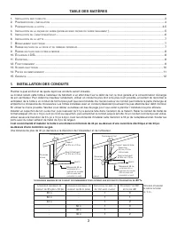
3 TABLE OF CONTENTS 1. I NSTALL DUCTWORK ................................................................................................................................................................ 3 2. P REPARE THE INSTALLATION ......................................................................
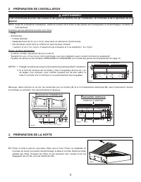
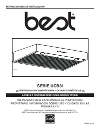
4 2. PREPARE THE INSTALLATION NOTE: Before proceeding to the installation, check the contents of the box. If items are missing or damaged, contact the manufacturer. Make sure that the following items are included: - Hood- Accessories: • 2 hybrid filters • 3¼” x 10” adapter/damper (located in one sty...
Best Range Hoods Manuals
-
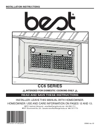 Best CC65I28SB
User Manual
Best CC65I28SB
User Manual
-
 Best CP34I429SB
User Manual
Best CP34I429SB
User Manual
-
 Best CP35I309SB
User Manual
Best CP35I309SB
User Manual
-
Best CP35I369SB
User Manual
-
Best CP35I429SB
User Manual
-
Best CP37I482SB
User Manual
-
 Best CP55IQ369SB
User Manual
Best CP55IQ369SB
User Manual
-
Best CP55IQ429SB
User Manual
-
Best CP57E362SB
User Manual
-
Best CP57E482SB
User Manual
-
Best CP57E602SB
User Manual
-
Best CP57IQT369SB
User Manual
-
Best CP57IQT482SB
User Manual
-
Best CP57IQT489SB
User Manual
-
Best CP57IQT542SB
User Manual
-
Best CP57IQT602SB
User Manual
-
Best CP57IQT662SB
User Manual
-
 Best CPD9M363SB
User Manual
Best CPD9M363SB
User Manual
-
 Best CPDI362SB
User Manual
Best CPDI362SB
User Manual
-
Best CPDI482SB
User Manual