Page 2 - Work Area; Keep your work area clean and well lit.; Electrical Safety; xxxx; Personal Safety; Power Tool Safety Rules
Read and understand all instructions . Failure to follow all instructions listed below, may result in electric shock, fire and/or serious personal injury. SAVE THESE INSTRUCTIONS - 2- Work Area Keep your work area clean and well lit. C l u t t e r e d b e n c h e s a n d d a r k a r e a s i n v i t ...
Page 3 - Safety Rules for Routers; serviced before using.; Service; I f c u t t i n g i n t o
-3- Safety Rules for Routers Do not force tool. Use the correct tool foryour application. The correct tool will do the job better and safer at the rate for which it isdesigned. Do not use tool if switch does not turn it“ON” or “OFF”. Any tool that cannot be controlled with the switch is dangerous an...
Page 4 - WARNING
t h e t o o l f r o m t h e t o p , t h e b i t r o t a t e sclockwise. Feed direction of cutting mustbe counter-clockwise. NOTE: inside and o u t s i d e c u t s w i l l r e q u i r e d i f f e r e n t f e e dd i r e c t i o n , r e f e r t o s e c t i o n o n f e e d i n g t h er o u t e r . F e e...
Page 5 - Symbols
-5- IMPORTANT: Some of the following symbols may be used on your tool. Please study them and learn their meaning. Proper interpretation of these symbols will allow you to operate thetool better and safer. Symbol Name Designation/Explanation V Volts Voltage (potential) A Amperes Current Hz Hertz Freq...
Page 6 - Functional Description and Specifications; . Such preventive safety; Routers
-6- Functional Description and Specifications D i s c o n n e c t t h e p l u g f r o m t h e p o w e r s o u r c e b e f o r e m a k i n g a n yassembly, adjustments or changing accessories . Such preventive safety measures reduce the risk of starting the tool accidentally. ! WARNING FIG. 1 SPEED C...
Page 7 - Model number
-7- 2 1 0 IN 50 40 30 20 10 0 MM FIG. 3 SPEED CONTROL DIAL Model 1617EVSP only SUB-BASE PLUNGE HANDLE CHIP DEFLECTOR MOTOR HOUSING ROCKER ON\OFF SWITCH MOTOR ALIGNMENT ARROW AIR VENTS BIT ROTATION ARROW BASE TYPE P Model number 1617 & 1618 1617EVS & 1618EVS 0 601 617 061 Voltage rating 120V ...
Page 8 - Assembly; INSTALLING A ROUTER BIT
-8- Assembly A wide assortment of router bits with differentp r o f i l e s i s a v a i l a b l e s e p a r a t e l y . U s e 1 / 2 "shank whenever possible, and only use goodquality bits. To prevent personal injury,a l w a y s r e m o v e t h e p l u g from power source before removing orinstal...
Page 9 - MOTOR
REMOVING MOTOR FROM BASE To remove motor from non-plunge bases:(Fig. 6) 1. Hold router in horizontal position, open b a s e c l a m p l e v e r , d e p r e s s c o a r s eadjustment lever, and pull motor upwardsuntil it stops. 2. Turn motor counter-clockwise, and gently pull it free of base. To remo...
Page 10 - TEMPLET GUIDE; • To position switch on the left, line up the
CHIP DEFLECTOR A l w a y s w e a r e y ep r o t e c t i o n . T h e c h i p d e f l e c t o r i s n o t i n t e n d e d a s a s a f e t yguard. The chip deflectors help keep dust and chipsout of your face, it will not stop objects largerthan dust thrown from the bit. To remove chip shield from bases...
Page 11 - Operating Instructions
B o s c h r o u t e r s a r e d e s i g n e d f o r s p e e d ,a c c u r a c y a n d c o n v e n i e n c e i n p e r f o r m i n gcabinet work, routing, fluting, beading, cove-cutting, dove tails, etc. They will enable youto accomplish inlay work, decorative edgesand many types of special carving. D...
Page 12 - DEPTH ADJUSTMENT WITH PLUNGE BASE; PLUNGING ACTION; W i t h t h e b i t i n s t a l l e d , g e n t l y l o w e r t h e
-12- T h e R A 1 0 0 2 F i n e A d j u s t m e n t C o n t r o lExtension, an optional accessory for the non-plunge bases, allows fine adjustment fromb e y o n d t h e t o p o f t h e m o t o r h o u s i n g . T oinstall, simply press the RA1002 into the endo f t h e b a s e ’ s o w n f i n e a d j ...
Page 13 - • When micro-adjusting the plunge depth, it
DEEP CUTS For deeper cuts, make several progressivelydeeper cuts by starting with the highest stepon the depth turret, and after each cut, rotatethe depth turret to progressively lower stepsas desired, until the final depth (lowest stepor flat) is reached. Steps progress by 1/8”increments. To be cer...
Page 14 - DIAL
-14- ROCKER “ON/OFF” SWITCH Your tool can be turned “ON” or “OFF” by therocker switch located on the motor housing.One side of the switch is marked “I” for “ON“,and the other side of switch is marked “O” for“OFF“. Also the edge of switch displays redwhen switch is in the “ON“ position. TO TURN THE T...
Page 15 - FEEDING THE ROUTER; Wrong direction of feed — hard to control.; RATE OF FEED
FEEDING THE ROUTER As seen from the top of the router, the bitturns clockwise and the cutting edges faceaccordingly. Therefore, the most efficient cutis made by feeding the router so that the bitt u r n s i n t o t h e w o r k , n o t a w a y . F i g u r e 1 5shows proper feed for various cuts. How ...
Page 16 - I n s e r t t h e p a n - h e a d s c r e w s , n o t t h e; PLUNGE BASE
CENTERING THE SUB-BASE AND TEMPLET GUIDES Your router features the Bosch “PrecisionCentering Design”. Its sub-base is preciselycentered at the factory. This positions the bitat the center of the sub-base and optionaltemplet guides. Precision centering allowsyou to closely follow jigs such as straigh...
Page 20 - DELUXE ROUTER GUIDE
-20- DELUXE ROUTER GUIDE (Not included, available as accessory) The Bosch deluxe router guide is an optionalaccessory that will guide the router parallel toa straight edge or allow you to create circlesand arcs. The deluxe router guide is supplied with tworods and screws to fasten the guide (Fig. 27...
Page 21 - Damage to plunge; FEEDING THE WORKPIECE ON A; F o r c l a r i t y , g u a r d a n d f e a t h e r b o a r d; CAUTION
USE IN ROUTER TABLE Your router can also be used in a routertable. The RA1160 fixed base is designed toallow easy depth adjustment in a table. TheRA1172 "D" D-Handle base will not fit inmost router tables. The RA1166 Plunge Basei s n o t r e c o m m e n d e d f o r use in a router table. Dam...
Page 22 - Accessories; W e; TOOL LUBRICATION; Cleaning; The tool may; Always wear safety goggles when; Maintenance; T h i s w i l l p r e v e n t
-22- Accessories Service P r e v e n t i v e m a i n t e n a n c eperformed by unauthorized personnel may result in misplacing ofi n t e r n a l w i r e s a n d c o m p o n e n t s w h i c hc o u l d c a u s e s e r i o u s h a z a r d . W e recommend that all tool service be performedby a Bosch Fac...
Page 23 - AVERTISSEMENT; Aire de travail; Avant de brancher; Sécurité des personnes; Règles de Sécurité Générales
-23- Vous devez lire et comprendre toutes les instructions. Le non-respect, même partiel, des instructions ci-après entraîne un risque de choc életrique, d'incendie et/ou de blessures graves. CONSERVEZ CES INSTRUCTIONS AVERTISSEMENT ! Aire de travail Veillez à ce que l'aire de travail soit propre et...
Page 24 - Réparation; Pour; Règles de sécurité concernant les toupies
-24- sécuritaire. Respectez aussi la vitesse de travail qui luiest propre. N'utilisez pas un outil si son interrupteur est bloqué. Un outil que vous ne pouvez pas commander par soninterrupteur est dangereux et doit être réparé. Débranchez la fiche de l'outil avant d'effectuer unréglage, de changer d...
Page 26 - Symboles
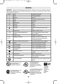
-26- Symboles IMPORTANT : Certains des symboles suivants peuvent être utilisés sur votre outil. Veuillez les étudier et apprendre leur signification. Une interprétation appropriée de ces symboles vous permettra d'utiliser l'outil defaçon plus efficace et plus sûre. Symbole Nom Désignation/Explicatio...
Page 27 - Description fonctionnelle et spécifications; Ces mesures de sécurité; Toupies
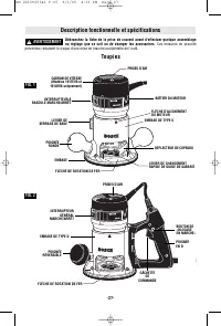
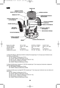
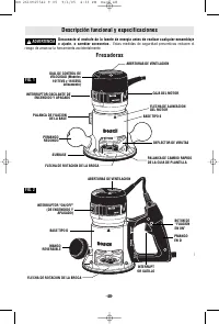
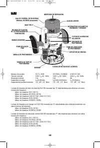
-27- Description fonctionnelle et spécifications Débranchez la fiche de la prise de courant avant d'effectuer quelque assemblageou réglage que ce soit ou de changer les accessoires. Ces mesures de sécurité préventive réduisent le risque d'une mise en marche accidentelle de l'outil. Toupies AVERTISSE...
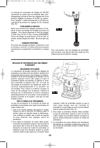
Page 29 - Utilisez ensuite la clé pour douille pour desserrer; l’écrou de douille en l’absence du fer.; La tige du fer et le mandrin doivent être; DÉPOSE DU FER; Au moyen des clés pour arbre et mandrin-douille; Assemblage
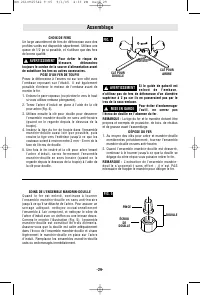
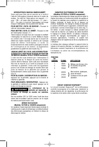
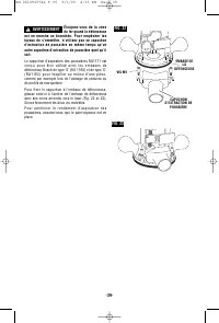
CHOIX DE FERS Un large assortiment de fers de défonceuse avec desprofiles variés est disponible séparément. Utilisez unequeue de 1/2 po si possible, et n’utilisez que des fersde bonne qualité. Pour éviter le risque deblessure, débranchez toujours le cordon de la source d’alimentation avantde substit...
Page 30 - BOÎTIER DU MOTEUR
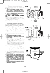
DÉMONTAGE DU MOTEUR DE L’EMBASE P o u r d é m o n t e r l e m o t e u r d e s e m b a s e s n o nplongeantes : (Fig. 6) 1. Tenez la défonceuse à l’horizontale, desserrez le levier de bridage de l’embase, enfoncez le levier deréglage grossier de la profondeur et tirez le moteurvers le haut jusqu’à ce...
Page 31 - POSE DE L'ADAPTATEUR DU GUIDE DE GABARIT; ADAPTATEUR; DÉFLECTEUR DE COPEAUX
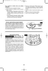
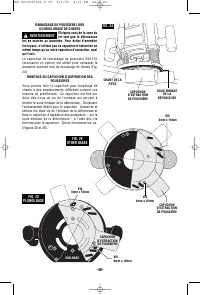
POSE DE L'ADAPTATEUR DU GUIDE DE GABARIT Placez l'adaptateur du guide de gabarit par-dessus lestrous au centre de l’embase, et alignez les deux trousfiletés au bas de l'adaptateur sur les trous fraisés del’embase. Fixez l'adaptateur à l'aide des vis fournies. Ilconvient de noter que l'adaptateur est...
Page 32 - Consignes de fonctionnement; RÉGLAGE DE LA PROFONDEUR AVEC EMBASE FIXE
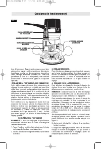
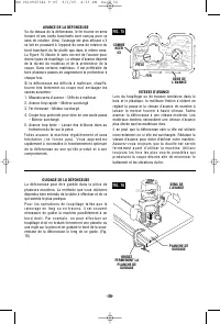
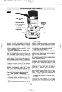
-32- Consignes de fonctionnement A B CADRAN DE RÉGLAGE DE PRÉCISION LEVIER DE SERRAGE DE LA BASE LEVIER DE RÉGLAGE GROSSIER ANNEAU INDICATEUR FIG.11 MARQUES INDICATRICES MOULÉES L e s d é f o n c e u s e s B o s c h s o n t c o n ç u e s p o u r f a i r eaisément du travail rapide et précis en ébéni...
Page 34 - USINAGES PROFONDS
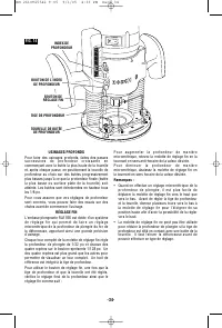
-34- 2 1 0 IN 50 40 30 20 10 0 MM FIG. 14 BOUTON DE L’INDEX DE PROFONDEUR INDEX DE PROFONDEUR TIGE DE PROFONDEUR TOURELLE DE BUTÉE DE PROFONDEUR BOUTON DE RÉGLAGE FIN USINAGES PROFONDS Pour faire des usinages profonds, faites des passess u c c e s s i v e s d e p r o f o n d e u r c r o i s s a n t ...
Page 37 - A = TROUS DE VIS NOYÉES; PLONGEANTES
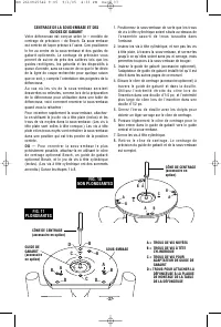
-37- CENTRAGE DE LA SOUS-EMBASE ET DES GUIDES DE GABARIT Votre défonceuse est conçue selon le « modèle de centrage de précision » de Bosch. Sa sous-embase est centrée de façon précise à l’usine. Ceci positionne le fer au centre de la sous-embase et des guides de gabarit optionnels. Le centrage de pr...
Page 41 - GUIDE DE DÉFONCEUSE DE LUXE
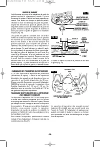
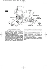
-41- GUIDE DE DÉFONCEUSE DE LUXE (Non compris, disponible en accessoire) L e g u i d e d e d é f o n c e u s e d e l u x e B o s c h e s t u n a c c e s s o i r e e n o p t i o n q u i g u i d e l a d é f o n c e u s e parallèlement à un chant droit ou qui vous permet de créer des cercles ou des arc...
Page 42 - MISE EN GARDE
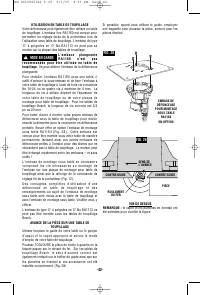
-42- UTILISATION EN TABLE DE TOUPILLAGE Votre défonceuse peut également être utilisée en table de toupillage. L’embase fixe RA1160 est conçue pour permettre un réglage facile de la profondeur lors de l’utilisation sous table de toupillage. L’embase de type ‘ D ’ à p o i g n é e s e n ‘ D ’ N o . R A...
Page 43 - DIMENSIONS DE RALLONGES RECOMMANDÉES
-43- Entretien Accessoires Service Tout entretien préventif effectué par des personnels non autorisés peut résulter en mauvais placement de fils internes ou de pièces, ce qui peut présenter un danger grave. Nous vous conseillons de faire faire tout l’entretien par un centre de service d’usine Bosch ...
Page 44 - Area de trabajo; Mantenga el área de trabajo limpia y bien iluminada.; Seguridad eléctrica; Antes de enchufar la; Seguridad personal; ADVERTENCIA; Normas de seguridad para herramientas mecánicas
-44- Lea y entienda todas las instrucciones. El incumplimiento de todas las instrucciones indicadas a continuación puede dar lugar a sacudidas eléctricas, incendios y/o lesiones personales graves. CONSERVE ESTAS INSTRUCCIONES Area de trabajo Mantenga el área de trabajo limpia y bien iluminada. Las m...
Page 45 - Servicio; Si el corte en paredes existentes u; Normas de seguridad para fresadoras
-45- No utilice la herramienta si el interruptor no laenciende o apaga. Toda herramienta que no se pueda controlar con el interruptor es peligrosa y debe serreparada. Desconecte el enchufe de la fuente de energía antesde hacer cualquier ajuste, cambiar accesorios oguardar la herramienta. Estas medid...
Page 47 - Símbolos
-47- Símbolos IMPORTANTE: Es posible que algunos de los símbolos siguientes se usen en su herramienta. Por favor, estúdielos y aprenda su significado. La interpretación adecuada de estos símbolos le permitirá utilizar laherramienta mejor y con más seguridad. Símbolo Nombre Designación/explicación V ...
Page 48 - Descripción funcional y especificaciones; Fresadoras
Desconecte el enchufe de la fuente de energía antes de realizar cualquier ensamblajeo ajuste, o cambiar accesorios. Estas medidas de seguridad preventivas reducen el riesgo de arrancar la herramienta accidentalmente. -48- Descripción funcional y especificaciones ADVERTENCIA ! Fresadoras FIG. 1 DIAL ...
Page 50 - Ensamblaje
CUIDADO DEL MANDRIL PORTAHERRAMIENTA Con la broca de fresadora retirada, continúe girandoel mandril portaherramienta en sentido contrario al del a s a g u j a s d e l r e l o j h a s t a s o l t a r l o d e l e j e . P a r aasegurarse de que el agarre sea firme, limpie de veze n c u a n d o e l m a ...
Page 51 - CAJA DEL MOTOR
-51- REMOCIÓN DEL MOTOR DE LA BASE Para quitar el motor de las bases que no sean dedescenso vertical: (Fig. 6) 1. Sujete la fresadora en posición horizontal, abra la palanca de fijación de la base, presione la palancade ajuste grueso y tire del motor hacia arriba hastaque se detenga. 2. Gire el moto...
Page 52 - ADAPTADOR DE
-52- P a r a i n s t a l a r e l m o t o r e n l a b a s e d e d e s c e n s overtical: 1. Suelte la palanca de fijación de la base. 2. Alinee la flecha que está en la base con la flecha que está en el motor (Fig. 8). • Para posicionar el interruptor en el lado derechode la base, alinee la flecha de...
Page 53 - Instrucciones de funcionamiento
-53- Las fresadoras Bosch están diseñadas para brindarvelocidad, precisión y conveniencia en la realizaciónde trabajo de armarios, fresado, estriado, molduradoc o n v e x o , c o r t e d e m o l d u r a s c ó n c a v a s , c o l a s d emilano, etc. Estas fresadoras le permitirán realizartrabajo de i...
Page 57 - AVANCE DE LA FRESADORA; El corte es demasiado grande para una pasada:; VELOCIDAD DE AVANCE
-57- AVANCE DE LA FRESADORA T a l c o m o s e v e d e s d e l a p a r t e d e a r r i b a d e l afresadora, la broca gira en el sentido de las agujas delr e l o j y l o s b o r d e s d e c o r t e e s t á n o r i e n t a d o scorrespondientemente. Por lo tanto, el corte máseficaz se realiza haciendo...
Page 58 - CONO DE CENTRADO
-58- CENTRADO DE LA SUBBASE Y LAS GUÍAS DE PLANTILLA La fresadora cuenta con el "Diseño de centrado dep r e c i s i ó n " d e B o s c h . S u s u b b a s e s e c e n t r a c o nprecisión en la fábrica. Esto posiciona la broca en elcentro de la subbase y las guías de plantilla opcionales.El c...
Page 61 - SUBBASE
-61- RECOLECCIÓN DE POLVO AL CONFORMAR BORDES No ponga las manos en el áread e l a b r o c a m i e n t r a s l a fresadora esté encendida o enchufada. Para evitarenredar las mangueras, no utilice esta cubierta dee x t r a c c i ó n d e p o l v o a l m i s m o t i e m p o q u e o t r acubierta de ext...
Page 62 - GUÍA DE FRESADORA DE LUJO
-62- GUÍA DE FRESADORA DE LUJO (No incluida, disponible como accesorio) La guía de fresadora de lujo Bosch es un accesorio opcional que guiará la fresadora paralela a un borde recto o le permitirá a usted crear círculos y arcos. La guía de fresadora de lujo se suministra con dos varillas y tornillos...
Page 63 - Para mayor claridad, el protector y la; PRECAUCION
-63- USO EN UNA MESA DE FRESADORA La fresadora también puede utilizarse en una mesa de fresadora. La base fija RA1160 está diseñada para permitir ajustar fácilmente la profundidad en una mesa. La base de mango en D tipo "D" RA1172 no cabrá en la mayoría de mesas de fresadora. La base de desc...
Page 64 - LUBRICACIÓN DE LAS HERRAMIENTAS; Limpieza; Use gafas de seguridad siempre que
-64- Mantenimiento Accesorios Servicio El mantenimiento preventivor e a l i z a d o p o r p e r s o n a l n o autorizado pude dar lugar a la colocación incorrectad e c a b l e s y c o m p o n e n t e s i n t e r n o s q u e p o d r í aconstituir un peligro serio. Recomendamos que todo el servicio de...