Page 2 - READ AND SAVE THESE INSTRUCTIONS; WARNING; INTENDED FOR DOMESTIC COOKING ONLY
- 3 - READ AND SAVE THESE INSTRUCTIONS WARNING TO REDUCE THE RISK OF FIRE, ELECTRIC SHOCK, OR INJURY TO PERSONS, OBSERVE THE FOLLOWING: 1. Use this unit only in the manner intended by the manufacturer. If you have questions, contact the manufacturer at the address or telephone number listed in the w...
Page 3 - CAUTION
- 4 - WARNING TO REDUCE THE RISK OF INJURY TO PERSONS IN THE EVENT OF A RANGE TOP GREASE FIRE, OBSERVE THE FOLLOWING:* 1. SMOTHER FLAMES with a close- fi tting lid, cookie sheet, or metal tray, then turn off the burner. BE CAREFUL TO PREVENT BURNS. If the fl ames do not go out immediately, EVACUATE ...
Page 4 - CLEANING AND MAINTENANCE; Motor
- 5 - CLEANING AND MAINTENANCE Proper maintenance of the Range Hood will assure proper performance of the unit. Motor The motor is permanently lubricated and never needs oiling. If the motor bearings make excessive or unusual noise, replace the motor with the exact service motor. The impeller should...
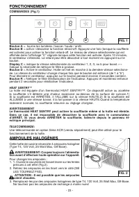
Page 5 - Button A
- 6 - OPERATION Controls (Fig.1) HALOGEN BULBS This range hood requires 4 halogen bulbs (Type T4, 120 Volt, 25 Watt Max, G9 Base). WARNING: Always switch off the electrical supply before carrying out any operation on the appliance. To change bulbs: 1. Open the cover by gently prying from proper slot...
Page 6 - PREPARE THE HOOD
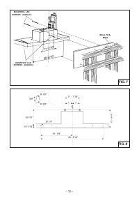
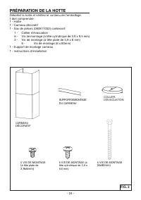
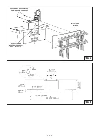
- 7 - PREPARE THE HOOD Unpack hood and check contents.You should receive: 1 - Hood1 - Decorative Flues1 - Parts Bag (080811032) containing: 1 - Duct Collar 6 - Mounting Screws (3,9 x 9,5mm Pan Head) 2 - Mounting Screws (3,9 x 6mm Flat Head) 6 - Mounting Lag Screws (6 x 60mm)1 - Flue Mounting Bracket...
Page 7 - INSTALL THE DUCTWORK
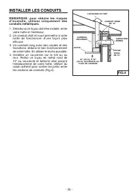
- 8 - INSTALL THE DUCTWORK NOTE: To reduce the risk of fi re, use only metal ductwork. 1. D e c i d e w h e r e t h e d u c t w o r k w i l l r u n between the hood and the outside. 2. A straight, short duct run will allow the hood to perform most ef fi ciently. 3. Long duct runs, elbows, and transi...
Page 10 - WIRING; wiring box cover; MOUNT THE DUCT COLLAR
- 11 - WIRING Note: This range hood must be properly grounded. The unit should be installed by a qualifi ed electrician in accordance with all applicable national and local electrical codes. 1. Remove the wiring box cover . Remove a knockout from the wiring box (Fig.10). 2. Secure the conduit to the...
Page 11 - Carefully
- 12 - I N S TA L L F L U E M O U N T I N G BRACKET 1. Carefully center the mounting bracket directly over the range hood location. 2. Secure the bracket to the wall using (2) 6 x 60mm mounting lag screws (Fig.11). Make sure the bracket is pushed into the corner, tight against the wall if necessary,...
Page 12 - INSTALL FILTERS
- 13 - FIG. 15 INSTALL FILTERS NOTE: Prior to use, remove protective fi lm from the fi lter frame. 1. To remove the GREASE fi lter, (Fig.15) push the fi lter towards the front so that it clears the fi lter channel, then pull down on the handle to disengage the fi lter from the hood. Tilt the fi lter...
Page 13 - CALIBRATE IQ BLOWER SYSTEM
- 14 - CALIBRATION LIGHT CALIBRATION BUTTON CALIBRATE IQ BLOWER SYSTEM TM INTERNAL BLOWER DUCTED UNITS ONLY After the hood is installed and wired, engage the calibration process (our Guaranteed Performance System Technology to ensure full-rated air fl ow is being delivered). Prior to calibration, en...
Page 15 - DESCRIPTION; SERVICE PARTS; MODEL WPB9
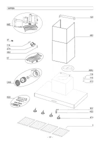
- 16 - KEY NO. PART NO. DESCRIPTION 9 B08087951 Grease Filters 37 B02300804 Heat Sentry 67 B06102611 Wires Assembly 114 B03292499 Runner Wires 115 BE3350233 Wiring Box 116 BE3334252 Wiring Box Cover 120 BE3353371 Flue mounting Bracket 202 B03292290 Wire Clamp 274 B03295035 Fuse Box 415 B03292596 Fai...
Page 17 - Modèle
- 18 - Modèle WPB9 ENGLISH........................................ 3 FRANÇAIS................................... 18 ESPAÑOL.................................. ...35 Aux États-Unis - BEST Hartford, WisconsinAu CANADA - BEST Drummondville, QC, Canada ENREGISTREZ VOTRE PRODUIT EN LIGNE À : www.BestRange...
Page 19 - LIRE CES DIRECTIVES ET LES CONSERVER; CONÇUE POUR LES CUISINES PRIVÉES UNIQUEMENT
- 20 - LIRE CES DIRECTIVES ET LES CONSERVER CONÇUE POUR LES CUISINES PRIVÉES UNIQUEMENT ! ! AVERTISSEMENTS POUR RÉDUIRE LES RISQUES D’INCENDIE, D’ÉLECTROCUTION OU DE BLESSURES PHY-SIQUES, RESPECTEZ LES INSTRUCTIONS CI-DESSOUS : 1. Utilisez cet appareil uniquement de la manière prévue par le fabrican...
Page 20 - AVERTISSEMENTS; ATTENTION
- 21 - AVERTISSEMENTS POUR RÉDUIRE LE RISQUE DE BLESSURES PHYSIQUES EN CAS DE FEU DE FRITURE SUR LA TABLE DE CUISSON, VEUILLEZ PROCÉDER COMME SUIT :* 1. ÉTOUFFEZ LES FLAMMES avec un couvercle hermétique, une plaque à biscuits ou un plateau en métal, puis éteignez le brûleur. SOYEZ PRUDENT(E) AFIN D’...
Page 21 - NETTOYAGE ET ENTRETIEN; Moteur
- 22 - NETTOYAGE ET ENTRETIEN Pour assurer les performances de l’appareil, entretenez-le de manière appropriée. Moteur Le moteur est lubri fi é en permanence et aucun graissage n’est nécessaire. Si les roule- ments du moteur font un bruit excessif ou inhabituel, remplacez le moteur par une pièce de ...
Page 23 - PRÉPARATION DE LA HOTTE
- 24 - PRÉPARATION DE LA HOTTE Déballez la hotte et véri fi ez le contenu de l’emballage. Il doit comprendre : 1 - Hotte1 - Carneau décoratif1 - Sac de pièces (080811032) contenant: 1 - Collier d’évacuation 6 - Vis de montage (à tête cylindrique de 3,9 x 9,5 mm) 2 - Vis de montage (à tête plate de 3...
Page 24 - INSTALLER LES CONDUITS
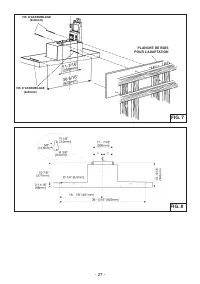
- 25 - INSTALLER LES CONDUITS REMARQUE: pour réduire les risques d ’ i n c e n d i e , u t i l i s e z u n i q u e m e n t d e s conduits métalliques. 1. Décidez où le tuyau doit être installé, entre votre hotte et l’extérieur. 2. Un conduit droit et court permettra à votre hotte de fonctionner d’un...
Page 25 - INSTALLEZ LA HOTTE
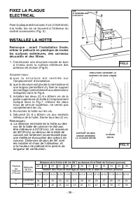
- 26 - FIG. 6 STRUCTURE DERRIÈRE LE SUPPORT EN BOIS CROISÉ SUPPORT EN BOIS CROISÉ DERRIÈRE LA CLOISON SÈCHE CLOISON SÈCHE FIG.5 FIXEZ LA PLAQUE ELECTRICAL Fixer la plaque elctrical avec 4 vis (3.9x9.5mm) à la hotte, les vis se trouvent à l’intérieur du sachet accessoires (Fig. 5). INSTALLEZ LA HOTTE...
Page 27 - INSTALLATION ELECTRIQUE; nexion électrique; FIXEZ LE COLLIER
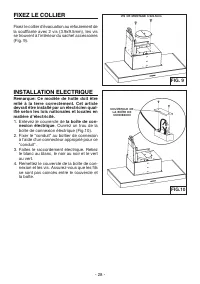
- 28 - INSTALLATION ELECTRIQUE Remarque: Ce modèle de hotte doit être relié à la terre correctement. Cet article devrait être installé par un électricien qual-ifi é selon les lois nationales et locales en matière d’électricité. 1. Enlevez le couvercle de la boîte de con- nexion électrique . Ouvrez u...
Page 28 - Centrez avec soin
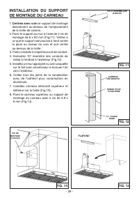
- 29 - INSTALLATION DU SUPPORT DE MONTAGE DU CARNEAU 1. Centrez avec soin le support de montage directement au-dessus de l’emplacement de la hotte de cuisine. 2. Fixez le support au mur à l’aide de 2 vis de montage de 6 x 60 mm (Fig.11). Veillez à ce que le support soit poussé à fond contre la paroi...
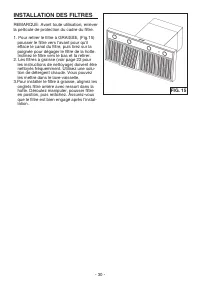
Page 29 - INSTALLATION DES FILTRES
- 30 - INSTALLATION DES FILTRES REMARQUE: Avant toute utilisation, enlever la pellicule de protection du cadre du fi ltre. 1. Pour retirer le fi ltre à GRAISSE, (Fig.15) pousser le fi ltre vers l’avant pour qu’il efface le canal du fi ltre, puis tirez sur la poignée pour dégager le fi ltre de la hot...
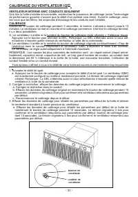
Page 30 - CALIBRAGE DU VENTILATEUR IQ
- 31 - LUMIÈRE DE CALIBRAGE BOUTON DE CALIBRAGE CALIBRAGE DU VENTILATEUR IQ MC VENTILATEUR INTERNE AVEC CONDUITS SEULEMENT Une fois la hotte installée et connectée, enclenchez le processus de calibrage (notre Technologie de performance garantie s’assure que le débit d’air optimal sera émis). Avant l...
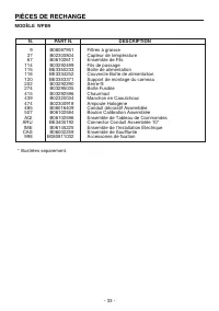
Page 32 - PIÈCES DE RECHANGE; MODÈLE WPB9
- 33 - N. PART N. DESCRIPTION 9 B08087951 Filtres à graisse 37 B02300804 Capteur de température 67 B06102611 Ensemble de Fils 114 B03292499 Fils de passage 115 BE3350233 Boîte de alimentation 116 BE3334252 Couvercle Boîte de alimentation 120 BE3353371 Support de montage du carneau 202 B03292290 Serr...
Page 34 - Modelo WPB9
- 35 - En EE.UU.: BEST Hartford, WisconsinEn CANADÁ - BEST Drummondville, QC, Canada Modelo WPB9 ENGLISH........................................ 3 FRANÇAIS................................... 18 ESPAÑOL.................................. ...35 REGISTRE SU PRODUCTO EN LÍNEA EN: www.BestRangeHoods.com/r...
Page 36 - LEA Y CONSERVE ESTAS INSTRUCCIONES; ADVERTENCIA; PARA COCINAS DOMÉSTICAS SOLAMENTE
- 37 - LEA Y CONSERVE ESTAS INSTRUCCIONES ADVERTENCIA PARA REDUCIR EL RIESGO DE INCENDIOS, DESCARGAS ELÉCTRICAS O LESIONES PERSONALES, RESPETE LO SIGUIENTE: 1. Utilice esta unidad sólo de la manera prevista por el fabricante. Si tiene preguntas, co- muníquese con el fabricante a la dirección o el nú...
Page 37 - PRECAUCIÓN
- 38 - ADVERTENCIA PARA REDUCIR EL RIESGO DE LESIONES PERSONALES EN CASO DE UN INCENDIO POR GRASA EN LA COCINA, RESPETE LO SIGUIENTE: * 1. SOFOQUE LAS LLAMAS con una tapa bien ajustada, una bandeja para hornear o una bandeja metálica y luego apague el quemador. TENGA LA PRECAUCIÓN DE EVITAR QUEMADUR...
Page 38 - LIMPIEZA Y MANTENIMIENTO
- 39 - LIMPIEZA Y MANTENIMIENTO El mantenimiento adecuado de la campana para cocina garantizará el rendimiento correc- to de la unidad. Motor El motor está constantemente lubricado y nunca necesita engrase. Si los cojinetes del mo- tor hacen un ruido excesivo o inusual, reemplace el motor con el mis...
Page 40 - PREPARACIÓN DE LA CAMPANA
- 41 - PREPARACIÓN DE LA CAMPANA Desensamble la campana y revise el contenido. Debe recibir: 1 - Campana1 - Chimenea decorativa1 - Bolsa de piezas (080811032) que contiene: 1 - Casquillo 6 - Tornillos de montaje (Cabeza troncocónica 3.9 x 9.5 mm) 2 - Tornillos de montaje (Cabeza plana 3.9 x 6 mm) 6 ...
Page 44 - INSTALACIÓN ELECTRICA; tapa de la caja de conexión; FIJAR EL CASQUILLO
- 45 - INSTALACIÓN ELECTRICA Nota: Este tipo de campana tiene que ser conectada a tierra cuidadosamente. L a u n i d a d d e b e i n s t a l a r l a u n t é c n i c o e l e c t r i c i s t a s i g u i e n d o l a s n o r m a s nacionales y locales. 1. Quite la tapa de la caja de conexión eléctrica y...
Page 45 - Cuidadosamente
- 46 - INSTALACION DEL SOPORTE DE MONTAJE 1. Cuidadosamente centre el soporte de montaje directamente sobre ubicación de campana de cocina. 2. Asegure el soporte a la pared utilizando los tornillos de montaje (2) 6 x 60mm (Fig.11). Asegúrese que el soporte este contra la esquina, junto con la pared ...
Page 47 - CALIBRACIÓN DEL VENTILADOR IQ
- 48 - LUZ DE CALIBRACION BOTON DE CALIBRACION CALIBRACIÓN DEL VENTILADOR IQ TM SOLO UNIDADES CON CONDUCTOS DE VENTILADOR INTERNO Después de instalar y cablear la campana, active el proceso de calibración (nuestra tecnología de sistema de desempeño garantizado, para asegurar que se suministre el fl ...
Page 49 - PIEZAS DE REPUESTO; MODELO WPB9
- 50 - N. PIEZA NO. DESCRIPCIÓN 9 B08087951 Filtros de grasa 37 B02300804 Sensor de temperatura 67 B06102611 Ensamble de cables 114 B03292499 Abrazadera de cables 115 BE3350233 Caja de alimentación eléctrica 116 BE3334252 Tapa de caja de alimentación eléctrica 120 BE3353371 Soporte de montaje 202 B0...