Page 2 - TO REDUCE THE RISK OF A RANGE TOP GREASE FIRE:; WARNING
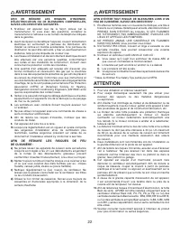
2 TO REDUCE THE RISK OF FIRE, ELECTRIC SHOCK OR INJURY TO PERSONS, OBSERVE THE FOLLOWING: 1. Use this unit only in the manner intended by the manufacturer. If you have questions, contact the manufacturer at the address or telephone number listed in the warranty. 2. Before servicing or cleaning unit,...
Page 3 - INTERIOR BLOWERS
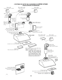
3 HL0220 - UP26M SERIES RANGE HOOD SYSTEM - INTERIOR BLOWERS M ODEL 647 (7” R OUND WALL CAP ) M ODEL 634 OR 644 ( ROOF CAP ) 8” R OUND STANDARD DUCT M ODEL 413 T RANSITION (3¼” X 10” TO 8”) M ODEL 459 TRANSITION (3¼” X 14” TO 8”) M ODEL 643 (8” R OUND WALL CAP ) A DAPTER / DAMPER 3¼” X 14” ( SUPPLIE...
Page 4 - IN-LINE AND EXTERIOR BLOWERS; HOOD
4 HL0071 - UP26M SERIES RANGE HOOD SYSTEM - IN-LINE AND EXTERIOR BLOWERS M ODEL 441 (10” R OUND WALL CAP ) M ODEL 437 (H IGH CAPACITY ROOF CAP ) M ODEL ILB9 (800 CFM ) OR ILB11 (1100 CFM ) I N - LINE BLOWER ( INCLUDES TWO 8” X 12” TO 10’’ ROUND TRANSITIONS ) M ODEL 418 (10” R OUND ADJUSTABLE ELBOW )...
Page 5 - SELECT BLOWER OPTION AND INSTALL DUCTWORK; Plan where and how the ductwork will be installed.
5 1. SELECT BLOWER OPTION AND INSTALL DUCTWORK Either an interior or exterior blower or in-line blower may be used with this hood. The Best UP26M must be installed with blower models iQ6, P3, P5, P6, P8, ILB3, ILB6, ILB9, ILB11, EB6, EB9, EB12 or EB15 only. Other blowers cannot be substituted. (Blow...
Page 6 - PREPARE INSTALLATION; PTIONAL
6 2. PREPARE INSTALLATION WARNING ! When performing installation, servicing or cleaning the unit, it is recommended to wear safety glasses and gloves. NOTE: Before proceeding to the installation, check the contents of the box. If items are missing or damaged, contact the manufacturer. Make sure that...
Page 7 - CAUTION; If using P5 blower, remove 10; LL; Remove tape on filters. Remove filters from hood and set aside.
7 6. CHOOSE THE OPENING (P5 AND P8 BLOWERS ONLY ) Removing horizontal knockout opening on back of hood. CAUTION If using P5 blower, remove 10 ” wide knockout. If using P8 blower, remove either 10 ” or 14 ” wide knockout. Remove the knockout for the chosen opening (horizontal at the back of the hood ...
Page 8 - YOU MUST; INTERIOR
8 10. INSTALL THE ADAPTER (P5 AND P8 BLOWERS ONLY ) Using provided screws, secure the adapter to the top (or back) of the hood. Seal the adapter to the hood using metal foil duct tape. NOTE: For vertical exhaust, ensure that the damper pivot is located towards the front of the hood. HD0005 HD0006 YO...
Page 9 - Connect cable into wiring box using wire connectors.; DO NOT FORGET TO CONNECT THE GROUND.; INTERIOR BLOWER
9 12. CONNECT WIRING (A LL BLOWERS ) WARNING ! Risk of electric shock. Electrical wiring must be done by qualified personnel in accordance with all applicable codes and standards. Before connecting wires, switch power off at service panel and lock service disconnecting means to prevent power to be s...
Page 10 - P5 BLOWER; FRONT
10 Install screws into the location as shown in the pictures below (P5 or P8 blower). Do not tighten screws down fully, leave a 1/8” gap. Hang blower unit onto blower plate (screws through the large part of the keyhole). Slide the blower to its position (screws in the small part of the keyhole). Tig...
Page 11 - Plug the power supply to the 3-prong male connector (; INSTALL THE CALIBRATION BUTTON BRACKET IN THE HOOD
11 14. INSTALL THE BLOWER (P3, P6, I Q6 AND EXTERIOR BLOWERS ONLY ) Refer to instructions included with blower. Once the blower is installed, plug the power supply to the 3-prong male connector ( A ) and the blower unit into the 2-prong female receptacle ( B ) inside the hood. 13. INSTALL THE BLOWER...
Page 12 - REINSTALL BOTTOM PANEL AND HYBRID BAFFLE FILTERS; LIGHT BULBS REPLACEMENT; disengage bulb leads from their grooves.
12 16. REINSTALL BOTTOM PANEL AND HYBRID BAFFLE FILTERS Reinstall bottom panel using both retaining screws removed in step 5. Reinstall filters. It is recommended to install side filters first and finish with center one(s). Insert the end with filter spring clip of hybrid baffle filter into the up...
Page 13 - Hood cleaning; Avoid when choosing a detergent:
13 18. USE AND CARE Hybrid baffle filters and impeller(s)* The hybrid baffle filters, impeller(s) and grease rail should be cleaned frequently. Use a warm detergent solution. Wash more often if your cooking style generates greater grease — like frying foods or wok cooking. Remove filters by pushing ...
Page 14 - HEAT SENTRYTM; BLOWER
14 19. OPERATION HEAT SENTRY™ This hood is equipped with a Heat Sentry™ thermostat. This thermostat is a device that will turn on or speed up the blower if it senses excessive heat above the cooking surface. 1) If blower is OFF - it turns blower ON to HIGH speed. 2) If blower is ON at a lower speed ...
Page 16 - IN-LINE OR EXTERIOR BLOWER
16 20. WIRING DIAGRAMS (CONT'D) IN-LINE OR EXTERIOR BLOWER 120 VAC M R EMOTE BLOWER ASSEMBLY BLU BLU HE0188A G G R OUND L INE N EUTRAL COLOR CODE BLK BLACKBLU BLUEG GREENW WHITEY YELLOW BLK GW BLK W W BLK BLK W R OUGH - IN P LATE W BLK BLK W BLK HS T HERMOSTAT F AN S WITCH BLK S PEED C ONTROL L AMP ...
Page 18 - CONT
18 21. SERVICE PARTS ( CONT ' D ) 5 1 2 3 4 5 6 7 8 9 10 11 12 6 13 14 15 16 17 18 19 20 21 22 23 HL0021 R EPLACEMENT P ARTS AND R EPAIRS In order to ensure your unit remains in good working condition, you must use Broan-NuTone genuine replacement parts only. Broan-NuTone genuine replacement parts a...
Page 21 - CONÇUE POUR USAGE DOMESTIQUE SEULEMENT; INSTALLATEUR : LAISSER CE GUIDE AU PROPRIÉTAIRE.; LIRE ET CONSERVER CES DIRECTIVES; GUIDE D’INSTALLATION
CONÇUE POUR USAGE DOMESTIQUE SEULEMENT INSTALLATEUR : LAISSER CE GUIDE AU PROPRIÉTAIRE. PROPRIÉTAIRE : DIRECTIVES D’UTILISATION ET D’ENTRETIEN EN PAGES 28 ET 29. LIRE ET CONSERVER CES DIRECTIVES BEST; Hartford, Wisconsin www.BestRangeHoods.com 800 558-1711BEST; Drummondville, QC, Canada www.BestRang...
Page 25 - SÉLECTIONNER L’OPTION VENTILATEUR ET INSTALLER LES CONDUITS
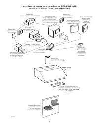
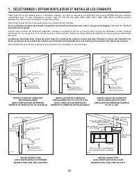
25 1. SÉLECTIONNER L’OPTION VENTILATEUR ET INSTALLER LES CONDUITS Cette hotte fonctionne autant avec un ventilateur intérieur, en ligne ou extérieur. La hotte Best de la série UP26M doit être installée uniquement avec l’un des ventilateurs suivants : iQ6, P3, P5, P6, P8, ILB3, ILB6, ILB9, ILB11, EB6...
Page 26 - PRÉPARER L’INSTALLATION; AVERTISSEMENT; - Accessoires : • Filtres à chicane avec poignées; PTIONNEL
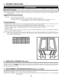
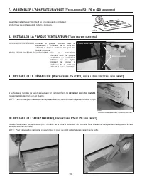
26 2. PRÉPARER L’INSTALLATION AVERTISSEMENT ! Il est recommandé de porter des lunettes et des gants de sécurité lors de l’installation, de l’entretien et de la réparation de cet appareil. NOTE : Avant de commencer l’installation, vérifier le contenu de la boîte. Si des pièces sont manquantes ou endo...
Page 27 - ATTENTION; RETIRER LES FILTRES ET LE PANNEAU INFÉRIEUR (T; OUS
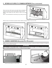
27 6. CHOISIR L’OUVERTURE (V ENTILATEURS P5 ET P8 SEULEMENT ) Retrait de l’ouverture préamorcée à l’arrière de la hotte. ATTENTION Si un ventilateur P5 est installé, retirer l’ouverture préamorcée de 10 po de largeur. Si un ventilateur P8 est installé, retirer l’ouverture préamorcée de 10 po ou cell...
Page 28 - le déviateur doit être installé
28 Si la hotte est montée de façon à évacuer l’air verticalement, le déviateur doit être installé . Installer le déviateur tel qu’il est illustré. NOTE : Il est normal que le déviateur n’entre pas entièrement dans la hotte; il dépasse d’environ 1/8 po. 9. INSTALLER LE DÉVIATEUR (V ENTILATEURS P5 ET ...
Page 29 - Refermer le couvercle.; VENTILATEUR INTÉRIEUR
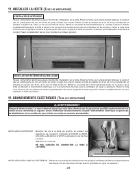
29 VENTILATEUR INTÉRIEUR : Brancher les fils à la boîte de jonction en utilisant les capuchons de connexion. Connecter le fil NOIR au NOIR, le BLANC au BLANC et le VERT ou dénudé à la vis de mise à la terre. Refermer le couvercle. NE PAS OUBLIER DE CONNECTER LA MISE À LA TERRE. VENTILATEUR EN LIGNE ...
Page 30 - VENTILATEUR P5; DEVANT
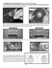
30 13. INSTALLER LE VENTILATEUR (V ENTILATEURS P5 ET P8 SEULEMENT ) Le ventilateur doit être installé à la plaque ventilateur en utilisant 4 vis de 3/8 po. Retirer le couvercle du ventilateur. Puis, retirer la (les)roue(s) du ventilateur en tirant délicatement (voir photos ci-dessous). HD0021 HD0022...
Page 31 - INSTALLER LE SUPPORT DU BOUTON DE CALIBRATION DANS LA HOTTE
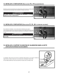
31 14. INSTALLER LE VENTILATEUR (V ENTILATEURS P3, P6, I Q6 ET EXTÉRIEURS SEULEMENT ) Pour installer le ventilateur, voir les instructions comprises avec celui-ci. Une fois installé, brancher le cordon de la boîte de jonction ( A ) à la fiche à 3 broches et le ventilateur ( B ) à la prise derrière l...
Page 32 - REMPLACEMENT DES LAMPES HALOGÈNES; NOTE : Pour obtenir une meilleure prise de l’ampoule lors de son
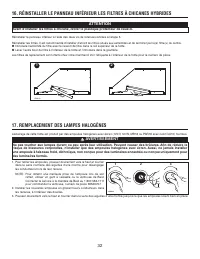
32 ATTENTION Avant d’installer les filtres à chicane, retirer le plastique protecteur de ceux-ci. 16. RÉINSTALLER LE PANNEAU INFÉRIEUR LES FILTRES À CHICANES HYBRIDES Réinstaller le panneau inférieur à l'aide des deux vis de retenues retirées à l'étape 5. Réinstaller les filtres. Il est recommandé d...
Page 33 - Nettoyage de la hotte
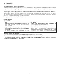
33 18. ENTRETIEN Filtres à chicane hybride et roue(s) de ventilateur* Les filtres, la gouttière et la (les) roues de ventilateur doivent être fréquemment nettoyés. Utiliser une solution d’eau chaude et de détergent. Nettoyer les filtres à chicane hybrides plus souvent si vos habitudes de cuisson gén...
Page 35 - SCHÉMAS ÉLECTRIQUES
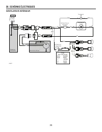
35 20. SCHÉMAS ÉLECTRIQUES VENTILATEUR INTÉRIEUR 120 VCA M ISE À LA TERRE L IGNE N EUTRE CODE DES COULEURS BLA BLANCBLE BLEUJ JAUNEN NOIRV VERT N V BLA N BLA BLA N N BLA M V ENTILATEUR INTERNE P LAQUE DU VENTILATEUR BLA N N BLA N BLE BLE T HERMOSTAT HS I NTERRUPTEUR DU VENTILATEUR N C ONTRÔLE DE VIT...
Page 36 - VENTILATEUR EXTÉRIEUR OU EN LIGNE
36 20. SCHÉMAS ÉLECTRIQUES (SUITE) VENTILATEUR EXTÉRIEUR OU EN LIGNE 120 VCA M ISE À LA TERRE L IGNE N EUTRE CODE DES COULEURS BLA BLANCBLE BLEUJ JAUNEN NOIRV VERT N V BLA N BLA BLA N N BLA M V ENTILATEUR EXTERNE P LAQUE DU VENTILATEUR BLA N N BLA N BLE BLE T HERMOSTAT HS I NTERRUPTEUR DU VENTILATEU...
Page 37 - PIÈCES DE REMPLACEMENT
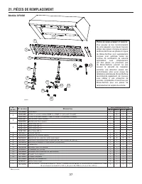
37 21. PIÈCES DE REMPLACEMENT Modèle UP26M HL0221 2 10 1 3 4 5 6 7 8 9 11 12 13 14 15 * N ON ILLUSTRÉ . P IÈCES DE REMPLACEMENT ET SERVICE Pour assurer le bon fonctionnement de votre appareil, vous devez toujours utiliser des pièces d’origine provenant de Broan-NuTone. Les pièces d’origine de Broan-...
Page 38 - SUITE
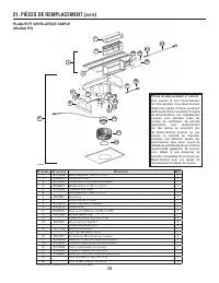
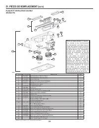
38 21. PIÈCES DE REMPLACEMENT ( SUITE ) 5 1 2 3 4 5 6 7 8 9 10 11 12 6 13 14 15 16 17 18 19 20 21 22 23 HL0021 N° DE RÉF . N° DE PIÈCE D ESCRIPTION Q TÉ 1 SV13296 A DAPTATEUR / VOLET 3¼ PO X 10 PO 1 2 SV03500 D ÉFLECTEUR D ' AIR 1 3 SV12997 P LAQUE VENTILATEUR SIMPLE ASSEMBLÉE 1 4 SV03577 M OUSSE 1/...
Page 41 - EXCLUSIVAMENTE PARA COCINAS DOMÉSTICAS; INSTALADOR: ENTREGUE ESTE MANUAL AL PROPIETARIO DE LA CASA.; LEA ESTAS INSTRUCCIONES Y GUÁRDELAS; INSTRUCCIONES DE INSTALACIÓN
EXCLUSIVAMENTE PARA COCINAS DOMÉSTICAS INSTALADOR: ENTREGUE ESTE MANUAL AL PROPIETARIO DE LA CASA. PROPIETARIO: INFORMACIÓN SOBRE UTILIZACIÓN Y CUIDADO EN LAS PÁGINAS 53 Y 54. LEA ESTAS INSTRUCCIONES Y GUÁRDELAS ! ! SERIE UP26M BEST; Hartford, Wisconsin www.BestRangeHoods.com 800-558-1711BEST; Drumm...
Page 43 - CAMPANA
43 M ODELO 647 (R EMATE DE PARED DE 7” REDONDO ) M ODELO 634 Ó 644 (R EMATE DE TECHO ) M ODELO 643 (R EMATE DE PARED DE 8” REDONDO ) HL0220 - SISTEMA DE LA CAMPANA DE COCINA SERIE UP26M - VENTILADOR INTERIOR C ODO ESTÁNDAR DE 8" REDONDO M ODELO 413 T RANSICÍON (3¼” X 10” A 8”) M ODELO 459 T RANS...
Page 45 - SELECCIONE LA OPCIÓN VENTILADOR Y INSTALE LOS CONDUCTOS; Planifique dónde y como se van a colocar los conductos.; La distancia mínima entre la campana y la encimera debe ser de 24
45 1. SELECCIONE LA OPCIÓN VENTILADOR Y INSTALE LOS CONDUCTOS Esta campana funciona tanto con un ventilador exterior, con un ventilador en línea y como interior. La campana de modelo Best UP26M debe ser instalado unicamente con ventilador modelo iQ6, P3, P5, P6, P8, ILB3, ILB6, ILB9, ILB11, EB6, EB9...
Page 46 - PREPARE LA INSTALACIÓN; ADVERTENCIA; Asegúrese que los artículos siguientes están incluidos:; INSTALE LA PLACA PARA SALPICADURAS (O; PCIONAL
46 2. PREPARE LA INSTALACIÓN ADVERTENCIA ! Se aconseja llevar anteojos y guantes de seguridad al instalar, reparar o limpiar el aparato. NOTA: Antes de comenzar la instalación, verificar el contenido de la caja. Si alguna pieza falta o está dañada, póngase en contacto con el fabricante. Asegúrese qu...
Page 47 - PRECAUCIÓN; Si un ventilador P5 es instalado, quite la abertura de 10; ENTILADORES; DESMONTAJE DE LOS FILTROS HÍBRIDOS Y DEL TABLERO INFERIOR (; TODOS; NOTA: Se aconseja empezar por el filtro o filtros centrales.
47 Rompación de la abertura horizontal detrás de la campana. PRECAUCIÓN Si un ventilador P5 es instalado, quite la abertura de 10 ” de anchura. Si un ventilador P8 es instalado, quite la abertura de 10 ” o de 14 ” de anchura. A BERTURA DE 14” A BERTURA DE 10” HD0076 A BERTUR A DE 14” HD0077 A BER TU...
Page 48 - USTED DEBE; desviador tal como ilustrado.; VENTILADOR EN LÍNEA O EXTERIOR: Referirse a los instrucciones
48 10. INSTALE EL ADAPTADOR (V ENTILADORES P5 Y P8 SOLAMENTE ) Utilizando los 2 tornillos estandar 1/2”, instale el adaptador encima o detrás de la campana. Luego selle el adaptador con la ayuda de una cinta adhesiva metálica para tubos. NOTA: Para una evacuación vertical, asegúrese que el pivote de...
Page 49 - VENTILADOR; VENTILADOR INTERIOR
49 ADVERTENCIA ! Peligro de choque eléctrico. La instalación eléctrica debe ser hecha por personal calificado de acuerdo con todos los códigos aplicables y normas. Antes de efectuar el empalme, cortar la alimentación eléctrica del interruptor y cerrar con securidad para prevenir una alimentación acc...
Page 50 - VENTILADOR P5; DELANTE
50 13. INSTALACIÓN DEL VENTILADOR (V ENTILADORES P5 Y P8 SOLAMENTE ) El ventilador debe ser instalado a la placa del ventilador utilizando 4 tornillos de 3/8”. Saque la tapa del ventilador. Saque la(s) rueda(s) del ventilador tirándola delicadamente (ver fotos de abajo). HD0021 HD0022 Instale los to...
Page 51 - Conecte el cable de la caja eléctrica (; INSTALE EL SOPORTE DEL BOTÓN DE CALIBRACIÓN EN LA CAMPANA
51 13. INSTALACIÓN DEL VENTILADOR (V ENTILADORES P5 Y P8 SOLAMENTE ) ( CONTINUACIÓN ) ADVERTENCIA ! Jamás conecte el cable eléctrico del ventilador con el enchufe del cable de alimentación. Conecte el cable de la caja eléctrica ( A ) y el cable del ventilador ( B ) a los enchufes detrás del panel de...
Page 52 - REINSTALACIÓN DEL TABLERO INFERIOR Y DE LOS FILTROS HÍBRIDOS; sentido antihorario para liberar el casquillo de sus ranuras.; SUSTITUCIÓN DE LAS BOMBILLAS
52 16. REINSTALACIÓN DEL TABLERO INFERIOR Y DE LOS FILTROS HÍBRIDOS Vuelva a instalar el tablero inferior con los dos tornillos de fijación retirados en el paso 5. Vuelva a instalar los filtros. Se aconseja instalar primero los filtros laterales y terminar por el/los filtro(s) central(es). Introdu...
Page 53 - Limpieza de la campana; blanqueador
53 18. MANTENIMIENTO Los filtros híbridos y la(s) rueda(s) del ventilador* Los filtros, canal y la rueda del ventilador deben ser frecuentemente limpiadas. Utilice una disolución de detergente con agua templada. Lávelos con mayor frecuencia si su tipo de cocina genera más grasa (alimentos fritos o c...
Page 55 - DIAGRAMAS ELÉCTRICOS
55 20. DIAGRAMAS ELÉCTRICOS VENTILADOR INTERIOR 120 VCA T IERRA H IL O N EUTR O Lí NEA N VB N B B N N B M V ENTILADOR INTERIOR P LACA DEL VENTILADOR B N N B N AZ AZ T ERMOSTATO HS I NTERRUPTOR DEL VENTILADOR N C ONTROL DE VELOCIDAD I NTERRUPTOR DE LÁMPARA AM B AM LÁMP ARA B AM HE0187E LÁMP ARA LÁMP ...
Page 56 - VENTILADOR EXTERIOR O EN LÍNEA
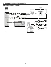
56 20. DIAGRAMAS ELÉCTRICOS (CONTINUACIÓN) VENTILADOR EXTERIOR O EN LÍNEA 120 VCA N VB N B B N N B M C ONJUNTO DE VENTILADOR EXTERIOR P LACA DEL VENTILADOR B N N B N AZ AZ N AM B AM B AM HE0188E N B V T IERRA H IL O N EUTR O Lí NEA T ERMOSTATO HS I NTERRUPTOR DEL VENTILADOR C ONTROL DE VELOCIDAD I N...
Page 58 - CONTINUACIÓN
58 21. PIEZAS ( CONTINUACIÓN ) 5 1 2 3 4 5 6 7 8 9 10 11 12 6 13 14 15 16 17 18 19 20 21 22 23 HL0021 N.° DE REF . N.° DE LA PIEZA D ESCRIPCIÓN C TD 1 SV13296 A DAPTADOR & COMPUERTA 3¼” X 10” 1 2 SV03500 D EFLECTOR DE AIRE 1 3 SV12997 M ONTAJE DE PLACA DE VENTILADOR SIMPLE 1 4 SV03577 E SPUMA 1/...