Baumatic BSGH95 Hob – User Manual, read for free online in PDF format. We hope this helps you resolve any issues you may have. If you have further questions, please contact us through the contact form.
1
2
3
4
5
6
7
8
9
10
11
12
13
14
15
16
Table of Contents:
Page 2 – DESCRIPTION OF COOKTOP
Page 3 – USE
Page 5 – CLEANING
Page 6 – INSTALLATION; COMPLY WITH THE DIMENSIONS; TECHNICAL INFORMATION; ) INSTALLING THE COOKTOP
Page 7 – ) FIXING THE COOKTOP
Page 9 – ) ELECTRICAL CONNECTION
Page 10 – ADJUSTMENTS
Page 11 – CONVERSIONS; ) UNIVERSAL LP GAS TO NATURAL GAS; ) NATURAL GAS TO UNIVERSAL LP GAS
Page 12 – 0) REPLACING THE INJECTORS; TABLE 1
Page 13 – SERVICING; CABLE TYPES AND SECTIONS
Page 14 – TECHNICAL ASSISTANCE AND SPARE PARTS
Loading the manual
Instructions and installation
manual
MODELS:
BSGH95-ANZ / BSGH75-ANZ
BSGH64-ANZ / BSGH32-ANZ
BSGH30-ANZ
PLEASE READ THIS MANUAL BEFORE
INSTALLING THE COOKTOP.
COD. 04067IR 26.02.2013
"Loading the manual" means you need to wait until the file loads and becomes available for online reading. Some manuals are very large, and the time they take to appear depends on your internet speed.
Summary
Page 2 - DESCRIPTION OF COOKTOP
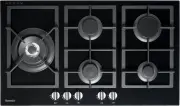
2 Natural U-LPG 1 Ultra rapid gas burner/WOK 14.5 MJ/h 12.6 MJ/h 2 Rapid gas burner 12.0 MJ/h 10.4 MJ/h 3 Semirapid reduced gas burner 5.4 MJ/h 4.9 MJ/h 4 Semirapid gas burner 7.1 MJ/h 6.3 MJ/h 5 Auxiliary gas burner 4.1 MJ/h 3.6 MJ/h 6 Pan stands support 2F 7 Pan stands support 1F 8 Burner n° 2 con...
Page 3 - USE
3 USE FIG. 1 FIG. 2 1) BURNERS A diagram is screen-printed above each knob on the front panel. This diagram indicates to which burner the knob in question corresponds. After having opened the gas mains or gas bottle tap, light the burners as described below: - automatic electrical ignition Push and ...
Page 5 - CLEANING
5 CLEANING IMPORTANT: Always disconnect the appliance from the gas and electricity mains before carrying out any cleaning operation. 2) COOKTOP P e r i o d i c a l l y w a s h t h e c o o k t o p , t h e pa n s ta n d support, the enamelled burner caps “C” and the burner heads “M” (see fig. 3) with ...
Page 6 - INSTALLATION; COMPLY WITH THE DIMENSIONS; TECHNICAL INFORMATION; ) INSTALLING THE COOKTOP
6 FIG. 4/A INSTALLATION FIG. 4 COMPLY WITH THE DIMENSIONS (in mm) A B C D E 1F-2F (30) 282 473 59 59 100 min. 4F (60) 553 473 63.5 63.5 173.5 min. 5F (70) 645 473 63.5 63.5 173.5 min. 5F (90) 833 475 62.5 62.5 73.5 min. TECHNICAL INFORMATION FOR THE INSTALLER This appliance shall be installed only b...
Page 7 - ) FIXING THE COOKTOP
7 4) FIXING THE COOKTOP The cooktop has a special seal which prevents liquid from getting into the cabinet. Strictly comply with the following instructions in order to correctly apply this seal: - Take off all the movable parts of the hob. - Cut the seal in 4 parts of the necessary lenght to positio...
Page 9 - ) ELECTRICAL CONNECTION
6) ELECTRICAL CONNECTION The appliance is supplied with a 1800 mm long flexible supply lead. The point of attachment for this lead is located at the rear and on the underside of the appliance 380 mm from the right hand side. The voltage and power consumption are detailed on the underside of the appl...
Page 10 - ADJUSTMENTS
ADJUSTMENTS Always disconnect the appliance from the electricity main before making any adjustments. All seals must be replaced by the technician at the end of any adjustments or regulations. Our burners do not require primary air adjustment. a) Data Label The Data Label is located on the underside ...
Page 11 - CONVERSIONS; ) UNIVERSAL LP GAS TO NATURAL GAS; ) NATURAL GAS TO UNIVERSAL LP GAS
11 CONVERSIONS 8) UNIVERSAL LP GAS TO NATURAL GAS CONVERSION PROCEDURE Appliance models: Gas stainless steel cooktop models: 1. Remove each burner cap and burner skirt. 2. Remove the Universal LP Gas main injector with a 7 mm/VF tube spanner and replace with the appropriate size Natural Gas injector...
Page 12 - 0) REPLACING THE INJECTORS; TABLE 1
12 CONVERSIONS 10) REPLACING THE INJECTORS The burners can be adapted to different types of gas by installing injectors suited to the type of gas required. To do this, first remove the burner tops using a wrench “B”. Now unscrew injector “A” (see fig. 10) and fit a injector corresponding to the type...
Page 13 - SERVICING; CABLE TYPES AND SECTIONS
13 FIG. 11 SERVICING Gas cooktop H05 RR - F Section 3 x 0.75 mm 2 TYPE OF TYPE OF SINGLE - PHASE COOKTOP CABLE POWER SUPPLY CABLE TYPES AND SECTIONS ATTENTION!!! If the power supply cable is replaced, the installer should leave the ground wire longer than the phase conductors (fig. 11) and comply wi...
Page 14 - TECHNICAL ASSISTANCE AND SPARE PARTS
14 TECHNICAL ASSISTANCE AND SPARE PARTS Before leaving the factory, this appliance will have been tested and regulated by expert and specialised personnel in order to guarantee the best performances. Any repairs or adjustments which may be subsequently required may only be carried out by qualified p...