Page 3 - IMPORTANT; INSTALLATION OR BY UNSUITABLE, WRONG OR ABSURD USE.
IMPORTANT The appliance must be connected by qualified technician in accordance with the applicable regulations. The data plate (a) of the oven is still visible after the appliance has been installed. This plate, which is visible when the oven door is open, contains all the identification data of th...
Page 4 - CONTENTS; of
CONTENTS INSTRUCTIONS FOR THE INSTALLER 3 INSTRUCTIONS FOR INSTALLATION OF THE APPLIANCE 3 POSITIONING 3 VENTILATION 3 GAS CONNECTION 3 RIGID PIPE CONNECTION 3 CONVERSION TO A DIFFERENT TYPE OF GAS 4 NOZZLE TABLE 4 ADJUSTMENT OF THE MINIMUM SETTING FOLLOWING CONVERSION TO A DIFFERENT GAS TYPE 5 FLUS...
Page 5 - (positioning and ventilation requirements); GAS CONNECTION
INSTRUCTIONS FOR THE INSTALLER INSTRUCTIONS FOR INSTALLATION OF THE APPLIANCE (positioning and ventilation requirements) The regulations covering the installation, maintenance and operation of gas appliances for domestic use are applicable regulations. An extract of these regulations appears below. ...
Page 6 - CONVERSION TO A DIFFERENT TYPE OF GAS
Important:Use two wrenches to turn the fitting “G” to the required position. When the fitting is in the desired position, firmly tighten nut “A” (Fig. 3). WARNING - IMPORTANT: after connecting the appliance to the gas supply (or to the liquid gas bottles) CHECK FOR LEAKS at the union using a solutio...
Page 7 - Injectors Table; REPLACING THE GAS GRILL NOZZLE
Injectors Table The diameters in hundredths of millimetre are stamped on the nozzle. Adjustment of the Minimum Setting Following Conversion to a different Gas Type Proceed to disassemble the front panel: - for the front panel, unscrew the two rear fixing screws- for glass fronts, unscrew the two loc...
Page 8 - FLUSH FITTING
FLUSH FITTING The oven can be installed under a work top or in a cooking column. The dimensions of the housing for the oven are given in figure 7.Make sure that surrounding materials are heat resistant. Align the oven centrally with respect to the side walls of the units surrounding it and fix it in...
Page 9 - ELECTRICAL CONNECTIONS
ELECTRICAL CONNECTIONS Before connecting the oven to the mains power supply,make sure that: 1) The supply voltage corresponds to the specifications on the data plate on the front of the oven. 2) The mains supply has an efficient earth (ground) connection complying with all applicable laws and regula...
Page 11 - Gas oven temperature control; OVEN TEMPERATURE CONTROL
DESCRIPTION OF THE FRONT CONTROL PANEL GAS OVEN WITH ELECTRIC GRILL CONTROLS (Fig. 12) 1.Gas oven temperature control 2. Grill, spit roaster and oven light knob 3.Gas oven indicator light 4.Mechanical timer 5.Grill indicator light OVEN TEMPERATURE CONTROL The temperature control knob serves to set t...
Page 17 - Guideline values for cooking with the grill:; REMOVAL OF THE BURNER COVER PLATE:; The oven light must have these precise features:
Guideline values for cooking with the grill: REMOVAL OF THE BURNER COVER PLATE: (see fig. 20) The burner cover plate is secured at the front by two tabs inserted in two slots; to remove the cover plate, raise the rear of the plate so that it pivots at the front and withdraw the tabs form the slots. ...
Page 18 - REMOVING THE OVEN DOOR; -Lift the door upwards and outwards to remove it from its mountings.; RESPECT FOR THE ENVIRONMENT
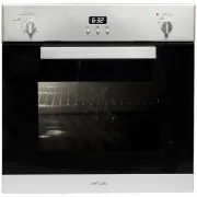
REMOVING THE OVEN DOOR The oven door can be removed quickly and easily.To do so, proceed as follows: -Open the door fully. -Lift the two levers shown in fig. 21. -Close the door as far as the first stop (caused by the raised levers). -Lift the door upwards and outwards to remove it from its mounting...
Page 19 - TIMER 3 BUTTONS; Setting the clock; Figure 1; To set the clock, press the central button when; Figure 2; oven will continue to work.
TIMER 3 BUTTONS Setting the clock Figure 1 “Auto” and “0:00” will start flashing when the unit is switched on for the first time. To set the clock, press the central button; when appears, press “+” or “-“ to set the correct time.After 5 seconds the symbol stop lighting and the hour is set (figure 1)...
Page 20 - Warranty Card; ffi
Warranty Card Worldwide Appliances Pty Limited A.B.N. 45868077422O ffi ce: 48-50 Moore Street, Leichhardt N.S.W 2040 Post:Locked Bag 3000, Annandale, N.S.W 2038 P: 1300 694 583WARRANTY REGISTRATION Your ongoing satisfaction with your artusi product is important to us. We ask that you complete the en...
Page 21 - MODEL NUMBER; (a) These terms and conditions do not affect your; continued
4 Please complete and send to ARTUSI at: REPLY PAID 83617 LEICHHARDT NSW 2040 Last Name: First Name: Address: State: Postcode: Email: Home Phone: Mobile: Purchase Date: / / (Please attach proof of purchase to validate warranty) MODEL NUMBER SERIAL NUMBER (if you cannot locate the serial number pleas...