Page 3 - Hood Specifications; Table of Contents
1 SAFETY NOTICE ................................................................. 2-3 LIST OF MATERIALS ....................................................... 4 INSTALLATION Ducting Calculation Sheet ....................................... 5 Mounting Height & Clearance ............................
Page 4 - Important Safety Notice; READ AND SAVE THESE INSTRUCTIONS
Important Safety Notice READ AND SAVE THESE INSTRUCTIONS 2 WARNING TO REDUCE THE RISK OF FIRE OR ELECTRIC SHOCK, DO NOT USE THIS FAN WITH ANY SOLID-STATE CONTROL DEVICE. WARNING TO REDUCE THE RISK OF FIRE ELECTRIC SHOCK, OR INJURY TO PERSONS, OBSERVE THE FOLLOWING: a. Use this unit only in the manne...
Page 5 - WARNING; CAUTION; Prop. 65 Warning for California Residents
Important Safety Notice 3 WARNING TO REDUCE THE RISK OF FIRE, USE ONLY METAL DUCTWORK. NOT FOR USE IN OUTDOOR COOKING ENVIRONMENTS. CAUTION To reduce risk of fire and to properly exhaust air outside - Do not vent exhaust air into spaces within walls, ceilings, attics, crawl spaces or garages. OPERAT...
Page 6 - PARTS SUPPLIED; List of Materials
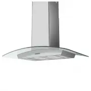
4 1 - Hardware package 1 - Top support frame 1 - Bottom support frame 2 - Top duct covers 2 - Bottom duct covers 1 - Hood body w/ blower (pre-installed) 1 - Canopy, glass 2 - Aluminum mesh filters 2 - 5W LED Light Strips 1 - 6” round damper (pre-installed) PARTS SUPPLIED HARDWARE PACKAGE CONTENTS PA...
Page 7 - Installation –
5 Duct pieces Total Equivalent number length x used = 3- 1/ 4” x 10” Rect., straight 1 Ft. x ( ) = Ft. 3- 1/ 4” x 10” Rect. to 6” round transition 5 Ft. x ( ) = Ft. 3- 1/ 4” x 10” Rect. to 6” round transition 90 0 elbow 20 Ft. x ( ) = Ft. 6”, 7”, 8”, 10” Round, 90 0 15 Ft. x ( ) = Ft. 6”, 7”, 8”, 10...
Page 8 - DUCTING
Installation – Mounting Height & Clearance 6 DUCTING A minimum of 6” round duct must be used to maintain maximum air flow efficiency. Always use rigid type metal ducts only. Flexible ducts could restrict air flow by up to 50%. Use calculation worksheet to compute total duct work (Page 5). ALWAYS...
Page 9 - WARNING FIRE HAZARD; Use single wall rigid Metal ductwork only.; Some Ducting Options; side wall cap
7 WARNING FIRE HAZARD NEVER exhaust air or terminate duct work into spaces between walls, crawl spaces, ceiling, attics or garages. All exhaust must be ducted to the outside, unless using the recirculating option. Use single wall rigid Metal ductwork only. Fasten all connections with sheet metal scr...
Page 10 - FRONT; (top of electrical box
8 Installation – Hood Specifications FRONT SIDE TOP of HOOD TOP SUPPORT FRAME (top view) 10 3/8 ” 23 15/16 ” 29 15/16 ”, 35 3/16 ” 25 9/16 ” 23-7/8” 3 1/ 2 ” 10 3/4 ” 1 3/4” 11 5/ 8 ” 4 5/ 8 ” Min. Ducted - 28”Min. Recirc. - 29”Maximum - 37” (top of electrical box ) 13 3/4 ” 5/16 ” C/L 6” 8” 8 3/ 4 ...
Page 11 - Hood is intended to be mounted to a finished ceiling.; WARNING: Electrical wiring must be done by a qualified person(s) in; PAPER TEMPLATE
9 Installation – Mounting the Hood Hood is intended to be mounted to a finished ceiling. 1. Ceiling Preparation: Determine hood mounting location and temporarily tape paper template (incluided with the hood) to the ceiling. Cut-out internal shaded area of template to allow the ductng and electrical ...
Page 12 - CAUTION: At least two installers are
10 Installation – Mounting the Hood 5. Remove tape securing electronics mounting bracket to hood. (FIG. D, #1) Remove (3) screws from top of hood body and set screws aside. Position electronics mounting bracket as show in (FIG. D, #2) and secure to hood body using the (3) previously removed screws. ...
Page 13 - Top Duct Covers; together by magnetic strips.
11 Installation – Mounting the Hood FIG. G 1 Top Duct Covers Top Support Frame Bottom Duct Covers Bottom Support Frame 10. Assemble Top Duct Covers (with louver holes) together over Top Support Frame, secure Top Duct Covers together by magnetic strips. Note: If using hood in ductless recirculating m...
Page 14 - back within the home.; RECIRCULATING KIT (REQUIRED IF NO DUCTING IS USED); Purchase recirculating kit per the part number above; Charcoal Filter Replacements; Hood Model; DO NOT WASH CHARCOAL FILTERS. Charcoal filters may need
12 Ductless recirculation is intended for applications where an exhaust duct work is not possible to be installed. When converted, the hood functions as a recirculating hood rather than an exhaust hood. Fumes and exhaust from cooking are drawn and filtered by a set of optional charcoal filters. The ...
Page 15 - Lights; Touch Controls
13 - On/Off off button will turn power on and off for the entire hood (fan and lights). - The hood will remember the last speed and light level it was last turned off at. - Delay Off Feature: With the fan on, press and hold the On/Off button for three seconds. The fan will change to speed 1 and auto...
Page 16 - Cleaning Stainless Steel; stainless steel grain.; Aluminum Mesh Filters; to soak if heavily soiled.; Removing Aluminum Mesh Filters; Maintenance –
14 SURFACE MAINTENANCE: Do not use corrosive detergents, abrasive detergents or oven cleaners. Do not use any product containing chlorine bleach or any product containing chloride. Do not use steel wool or abrasive scrubbing pads which will scratch and damage surface. Cleaning Stainless Steel Clean ...
Page 17 - LED LIGHT STRIPS; To replace LED light strip; Push the clip
15 LED LIGHT STRIPS In the unlikely event that your LED strip fails, please contact Zephyr to order replacement parts. See list of parts and accessories page for part #’s and contact information. To replace LED light strip 1. Remove aluminum mesh filters. 2. Remove light panel by two screws. 3. Disc...
Page 18 - ACT Conversion; By default the maximum blower CFM is set to 600.; the wiring diagram or in another clearly visible location.; To verify if your installer enabled ACT; - PC Board is located behind light panel.
16 ACT Conversion AIRFLOW CONTROL TECHNOLOGY (ACT) Some local codes limit the maximum amount of CFM a range hood can move. ACT allows you to control the maximum blower CFM of the range hood without the need for expensive make up air kits. ACT enables the installer to easily set the maximum blower sp...
Page 19 - iring Diagrams; Fan: 315W
17 W iring Diagrams Fan: 315W Lamp: LED 5W*2 Total: Max.325W @ 2.7A Voltage 120V 60Hz Power consumption UL file number: E127334 THERMALLY PROTECTED Model:BML-E30BG BML-E36BG Fan On/Off Lights
Page 20 - Troubleshooting; TROUBLESHOOTING PROCEDURES FOR BRISAS; Issue
18 Troubleshooting TROUBLESHOOTING PROCEDURES FOR BRISAS Issue Cause What to do After installation, the unit doesn’t work. 1. The power source is not turned ON. 1. Make sure the circuit breaker and the unit’s power is ON. 2. The power line and the cable locking connector is not connecting properly. ...
Page 21 - Accessories; DESCRIPTION; Replacement Parts; Aluminum Mesh Filter; Optional Accessories; Recirculating Kit
19 List of Parts & Accessories DESCRIPTION PART# Replacement Parts LED Light Strip, 5W Z0B0043 Aluminum Mesh Filter 50200043 Optional Accessories Recirculating Kit BRC-0007 Replacement Charcoal Filter Z0F-C094 Duct Cover Extension (up to 12’ ceiling) B1C-00ML To order parts, call us at 1.888.880...
Page 22 - arranty
20 W arranty OCT17.0301 Zephyr Ventilation, LLC (referred to herein as “we” or “us”) warrants to the original consumer purchaser (referred to herein as “you” or “your”) of Zephyr products (the “Products”) that such Products will be free from defects in materials or workmanship as follows: One Year L...