Simfer B6GM12016 - User Manual
Simfer B6GM12016 Oven – User Manual, read for free online in PDF format. We hope this helps you resolve any issues you may have. If you have further questions, please contact us through the contact form.
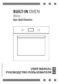
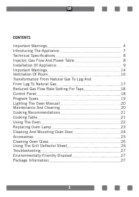
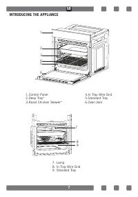
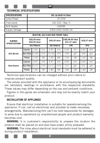
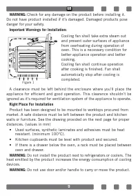
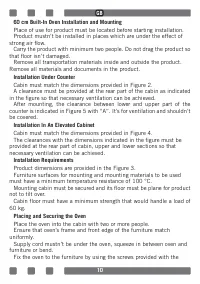

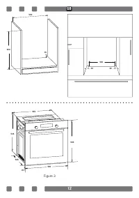
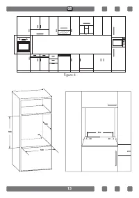
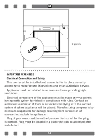
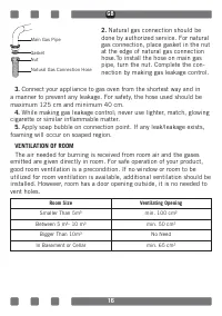
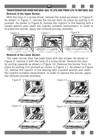
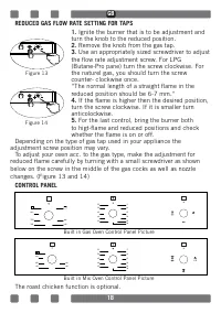
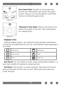
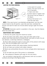
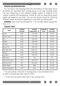
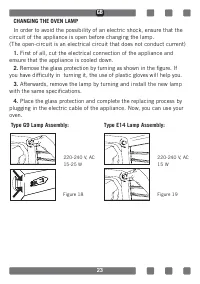
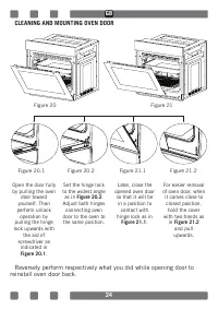
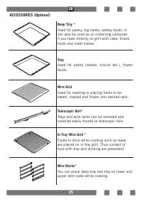
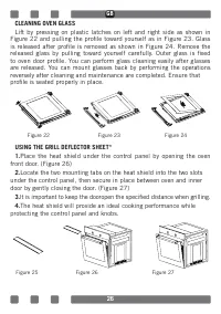
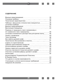
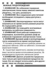
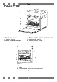
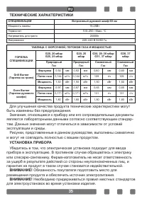
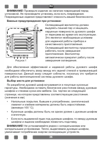
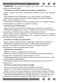
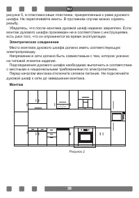
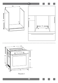
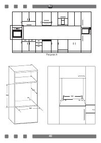
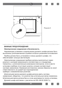
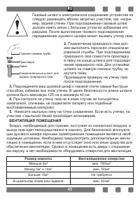
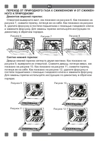
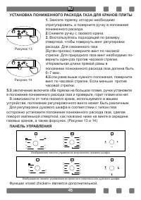
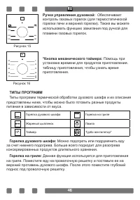
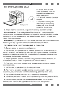
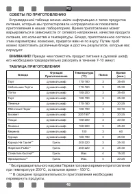
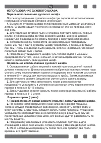
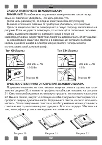
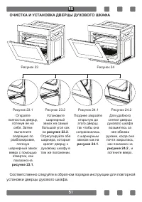
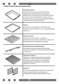
Table of Contents:
- Page 3 – CONTENTS; Technical Specifications
- Page 6 – Keep curtains, tissue paper or combustible; combustible materials in or on the appliance.; This appliance is not connected to a combustion
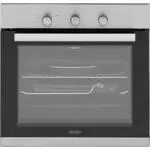
- Page 7 – INTRODUCING THE APPLIANCE; Tray
- Page 8 – TECHNICAL SPECIFICATIONS; SPECIFICATIONS; Lamp Power; Technical specifications can be changed without prior notice to
- Page 9 – WARNING: Check for any damage on the product before installing it.; danger for your safety.; Important Warnings for Installation:; after cooking is finished. Fan shall; WARNING: Do not use door and/or handle to carry or move the product.; Figure 1
- Page 11 – Mounting; Figure 2
- Page 12 – Figure 3
- Page 13 – Figure 4
- Page 14 – Figure 5
- Page 16 – cigarette or similar inflammable matter.; VENTILATION OF ROOM; Room Size; Smaller Than 5m3
- Page 17 – The lower burner door has been fixed with two screws. As shown in; Figure 8
- Page 18 – the flow rate adjustment screw. For LPG; For the last control, bring the burner both; to higt-flame and reduced positions and check; CONTROL PANEL; Built in Gas Oven Control Panel Picture; Built in Mix Oven Control Panel Picture
- Page 19 – function to flame the gas burners.; *Mechanical Timer Button: Helps to set time for the; food to be cooked in the oven. See cooking table
- Page 20 – LIGHTING THE OVEN MANUALL; Automatic switch is available in the oven.
- Page 21 – * Do not preheat. First half of cooking time is recommended to be
- Page 22 – slight smoke and smell might occur and that’s a normal situation.; Wipe inside of the oven with a slightly warm water with detergent; This gas oven’s top (grill) and bottom burner can only be used one at a; Once the burner is lit, you must continue to hold the knob in for
- Page 23 – First of all, cut the electrical connection of the appliance and; ensure that the appliance is cooled down.; Afterwards, remove the lamp by turning and install the new lamp; with the same specifications.; Type G9 Lamp Assembly: Type E14 Lamp Assembly:
- Page 24 – CLEANING AND MOUNTING OVEN DOOR; reinstall oven door back.
- Page 26 – profile is seated properly in place.; Locate the two mounting tabs on the heat shield into the two slots; protecting the control panel and knobs.
- Page 29 – СОДЕРЖАНИЕ
- Page 34 – ОПИСАНИЕ ПРИБОРА
- Page 36 – Рисунок 1
- Page 38 – Рисунок 2
- Page 39 – Рисунок 3
- Page 40 – Рисунок 4
- Page 41 – Рисунок 5
- Page 43 – ВЕНТИЛЯЦИЯ ПОМЕЩЕНИЯ; Размер комнаты; Не требуется
- Page 44 – демонтажу в обратном порядке.; Снятие нижней горелки:; Дверца нижней горелки затянута двумя винтами. Как показано на; Рисунок 8
- Page 47 – КАК ЗАЖЕЧЬ ДУХОВОЙ ШКАФ; ТЕХНИЧЕСКОЕ ОБСЛУЖИВАНИЕ И ОЧИСТКА
- Page 51 – ОЧИСТКА И УСТАНОВКА ДВЕРЦЫ ДУХОВОГО ШКАФА; установки дверцы духового шкафа.
H10-20-220-077 Rev 003
BUILT-IN OVEN
60cm
Gas And Electric
USER MANUAL
RU
GB
РУКОВОДСТВО ПОЛЬЗОВАТЕЛЯ
"Loading the manual" means you need to wait until the file loads and becomes available for online reading. Some manuals are very large, and the time they take to appear depends on your internet speed.
Summary
3 CONTENTS Important Warnings 4 Introducing The Appliance 7 Technical Specifications 8 Injector, Gas Flow And Power Table 8 Installation Of Appliance 9 Important Warnings 14 Ventilation Of Room 16 Transformation From Natural Gas To Lpg And From Lpg To Natural Gas 17 Reduced Gas Flow Rate Setting For...
6 23. Keep curtains, tissue paper or combustible (inflammable) materials away from appliance before starting to use it. Do not place inflammable or combustible materials in or on the appliance. 24. This appliance is not connected to a combustion product discharge system.This appliance shall be conne...
7 INTRODUCING THE APPLIANCE 1.Control Panel 4.In Tray Wire Grid 2.Deep Tray* 5.Standard Tray 3.Roast Chicken Skewer* 6.Oven door 7. Lamp8. In Tray Wire Grid9. Standard Tray 1 2 34 5 6 7 8 9 GB