Page 2 - TABLE OF CONTENTS
2 — English Introduction ..................................................................................................................................................................... 2 Warranty .................................................................................................
Page 3 - GENERAL SAFETY RULES; READ ALL INSTRUCTIONS
3 — English GENERAL SAFETY RULES WARNING: Read and understand all instructions. Failure to follow all instructions listed below, may result in electric shock, fire and/or serious personal injury. READ ALL INSTRUCTIONS KNOW YOUR POWER TOOL. Read the operator’s manual carefully. Learn the applicatio...
Page 5 - SPECIFIC SAFETY RULES; CALIFORNIA PROPOSITION 65
5 — English WARNING: This product and some dust created by power sanding, sawing, grinding, drilling, and other construction activities may contain chemicals, including lead, known to the State of California to cause cancer, birth defects, or other re-productive harm. Wash hands after handling. Some...
Page 6 - SYMBOLS
6 — English SYMBOLS Some of the following symbols may be used on this tool. Please study them and learn their meaning. Proper interpretation of these symbols will allow you to operate the tool better and safer. Safety Alert Indicates a potential personal injury hazard. Read Operator’s Manual To redu...
Page 7 - ELECTRICAL; EXTENSION CORDS
7 — English ELECTRICAL CONNECTION This product is powered by a precision-built electric motor. It should be connected to a power supply that is 120 V, AC only (normal household current), 60 Hz. Do not operate this product on direct current (DC). A substantial voltage drop will cause a loss of power ...
Page 8 - FEATURES
8 — English FEATURES PRODUCT SPECIFICATIONS Blade Width ................................................ 1/8 in. to 3/8 in.Blade Length .............................................................. 62 in.Frame to Blade Capacity .............................................. 9 in.Cutting Thickness C...
Page 9 - ASSEMBLY; LOOSE PARTS LIST; UNPACKING; MOUNTING BAND SAW TO WORKBENCH
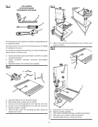
9 — English ASSEMBLY LOOSE PARTS LIST See Figure 4, page 18. The following items are included with the saw: Key No. Description Qty. A Saw Table ............................................................1 B Miter Gauge .........................................................1 C Hex key, 2 mm .......
Page 10 - MOUNTING THE SAW TABLE
10 — English ASSEMBLY MOUNTING THE SAW TABLE See Figures 6 - 7, pages 18 - 19. Remove the D-nut, washers, and wing screw on the saw table. Standing at the front of the band saw, slide the saw table past the blade and through the slot moving from the right side of the saw table to the left. Hol...
Page 11 - OPERATION; APPLICATIONS
11 — English OPERATION WARNING: Do not allow familiarity with tools to make you careless. Remember that a careless fraction of a second is sufficient to inflict serious injury. WARNING: Always wear eye protection with side shields marked to comply with ANSI Z87.1. Failure to do so could result in ob...
Page 13 - INSTALLING AND ADJUSTING THE BLADE; USING THE MITER GAUGE
13 — English ADJUSTMENTS WARNING: Before performing any adjustment, make sure the tool is unplugged from the power supply and the switch is in the off position. Failure to heed this warning could result in serious personal injury. WARNING: To avoid personal injury, maintain proper adjustment of blad...
Page 14 - ADJUSTING BLADE GUIDE ASSEMBLY; To Adjust Thrust Bearings:
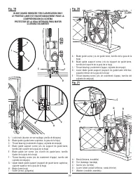
14 — English ADJUSTMENTS ADJUSTING BLADE GUIDE ASSEMBLY See Figures 17 - 18, page 21. To prevent the blade from twisting or breaking, the blade guide assembly should always be set approximately 1/8 in. above the workpiece. Turn the lock knob counterclockwise to unlock the blade guide assembly. A...
Page 15 - MAINTENANCE; LUBRICATION; BRUSH
15 — English MAINTENANCE LUBRICATION All of the bearings in this tool are lubricated with a sufficient amount of high grade lubricant for the life of the unit under normal operating conditions. Therefore, no further lubrication is required. MOTOR/ELECTRICAL Frequently vacuum or blow out sawdust fr...
Page 16 - TROUBLESHOOTING; PROBLEM CAUSE; FRENCH AND SPANISH LANGUAGE SECTIONS.
16 — English TROUBLESHOOTING PROBLEM CAUSE SOLUTION Motor will not run. 1. Problem with On/Off switch or 1. Have worn parts replaced before power cord. using band saw again. 2. Motor defective. 2. Do not attempt any repair. Have tool repaired by a qualified service technician. 3. Blade is binding. 3...
Page 17 - TABLE DES MATIÈRES; GARANTIE
2 – Français Introduction ..................................................................................................................................................................... 2 Garantie ................................................................................................
Page 18 - RÈGLES DE SÉCURITÉ GÉNÉRALES; LIRE TOUTES LES INSTRUCTIONS
3 – Français RÈGLES DE SÉCURITÉ GÉNÉRALES corps dans les pièces en mouvement. Des gants en caoutchouc et des chaussures antidérapantes sont recommandées pour le travail à l’extérieur. Les cheveux longs doivent être ramassés sous un couvre-chef. PORTEZ TOUJOURS DES LUNETTES DE SÉCURITÉ ÀCOQUES LATÉ...
Page 19 - RÈGLES DE SÉCURITÉ PARTICULIÈRES
4 – Français RÈGLES DE SÉCURITÉ GÉNÉRALES PROTÉGEZ VOTRE OUÏE. Portez des protège-tympan lors d’un usage prolongé de l’outil. LES LAMES TOURNENT SUR LEUR LANCÉE PENDANT QUELQUES INSTANTS APRÈS L’ARRÊT. N’UTILISEZ JAMAIS L’OUTIL DANS UNE ATMOSPHÈRE EXPLOSIVE. Les étincelles normales du moteur p...
Page 20 - PROPOSITION 65 DE L’ÉTAT DE CALIFORNIE
5 – Français RÈGLES DE SÉCURITÉ PARTICULIÈRES AVERTISSEMENT : Ce produit et la poussière dégagée lors du ponçage, sciage, meulage, perçage de certains matériaux et lors d’autres opérations de construction peuvent contenir des produits chimiques, notamment du plomb qui, selon l’État de la Californie,...
Page 21 - SYMBOLES; SYMBOLE
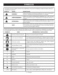
6 – Français SYMBOLES Certains des symboles ci-dessous peuvent être utilisés sur l’outil. Veiller à les étudier et à apprendre leur signification. Une interprétation correcte de ces symboles permettra d’utiliser l’outil plus efficacement et de réduire les risques. Symbole d’alerte de sécurité Indiqu...
Page 22 - CARACTÉRISTIQUES ÉLECTRIQUES; CORDONS PROLONGATEURS; CONNEXION ÉLECTRIQUE; VITESSE ET CÂBLAGE
7 – Français CARACTÉRISTIQUES ÉLECTRIQUES CORDONS PROLONGATEURS Utiliser exclusivement des cordons prolongateurs à trois fils doté d’une fiche à prise de terre brabchés sur une prise triphasée compatible avec la fiche de l’outil. Lors de l’utilisation d’un outil électrique à grande distance d’une pr...
Page 23 - CARACTÉRISTIQUES
8 – Français CARACTÉRISTIQUES FICHE TECHNIQUE Largeur de la lame .......... 3 mm à 10 mm (1/8 po à 3/8 po)Longueur de la lame ................................ 157,5 cm (62 po)Capacité entre la lame et le bâti .................. 229 mm (9 po)Hauteur de coupe maximale .................. 92 mm (3-5/8 p...
Page 24 - ASSEMBLAGE; LISTE DES PIÈCES DÉTACHÉE; DÉBALLAGE
9 – Français ASSEMBLAGE AVERTISSEMENT : Ne pas brancher avant d’avoir terminé l’assemblage. Le non-respect de cet avertissement peut causer un démarrage accidentel, entraînant des blessures graves. MONTAGE DE LA SCIE À RUBAN SUR UN ÉTABLI Si la scie à ruban doit être utilisée dans un endroit définit...
Page 25 - MONTAGE DE LA TABLE DE LA SCIE
10 – Français ASSEMBLAGE Montez la scie sur le panneau en utilisant les trous de la base de la scie comme gabarit. Positionnez et marquez les trousà l’endroit où la scie à ruban doit être montée. Suivez les trois dernières étapes de la section intitulée Montage de la scie à ruban sur un établi, ...
Page 26 - UTILISATION
11 – Français ASSEMBLAGE Faites encore tourner le volant supérieur à la main de quelques tours dans le sens horaire. Assurez-vous que la lame reste au même endroit sur les bandages. Refaites le réglage si nécessaire jusqu’à ce que la lame soit correctement centrée. Refermez bien le carter avant ...
Page 27 - AVANT DE QUITTER LA SCIE
12 – Français UTILISATION opérations comme la coupe de planches longues et lourdes. ARRÊTEZ la scie, enlevez la clé de l’interrupteur et débranchez la machine avant de la déplacer. Mettez l’interrupteur à la position « OFF » (ARRÊT) , puis retirez la clé d’interrupteur. Choisissez la bonne dim...
Page 28 - INCLINAISON DE LA TABLE; MONTAGE ET RÉGLAGE DE LA LAME
13 – Français UTILISATION INCLINAISON DE LA TABLE Voir figure 13, page 20. Desserrez légèrement la levier de verrouillage la table. Tournez le bouton de réglage de l’inclinaison vers du table de la scie jusqu’à obtention de l’angle voulu. En utilisant l’indicateur de l’échelle, vérifiez les in...
Page 29 - RÉGLAGE DE L’ENSEMBLE DE GUIDE-LAME; Réglage des roulements d’appui :
14 – Français RÉGLAGES RÉGLAGE DE L’ENSEMBLE DE GUIDE-LAME Voir les figures 17 et 18, page 21. L’ensemble de guide-lame doit toujours être réglé à environ 3 mm (1/8 po) au-dessus de la surface supérieure de la pièce à couper pour empêcher la lame de tourner ou de se casser. Tournez le levier de ve...
Page 30 - ENTRETIEN; LUBRIFICATION; Nettoyage des bandages:; BROSSE; ENTRETIEN GÉNÉRAL; PAGE APRÈS LES SECTIONS ESPAGNOL.
15 – Français ENTRETIEN LUBRIFICATION Tous les roulements de cet outil sont garnis d’une quantité de graisse de haute qualité, suffisante pour la durée de vie de l’outil, dans des conditions d’utilisation normales. Aucune autre lubrification n’est donc nécessaire. MOTEUR, ÉQUIPEMENT ÉLECTRIQUE. Pa...
Page 31 - RECHERCHE DE PANNES; PROBLÈME
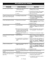
16 – Français RECHERCHE DE PANNES PROBLÈME CAUSE PROBABLE SOLUTION Le moteur ne pas fonctionne. 1. Problème dû à l’interrupteur ou au cordon d’alimentation. 1. Faites remplacer les pièces usées avant d’utiliser la scie à nouveau. 2. Moteur défectueu x. 3. Lame lie. 2. N’essayez pas de réparer. Faite...
Page 32 - ÍNDICE DE CONTENIDO; GARANTÍA
2 — Español Introducción ...................................................................................................................................................................... 2 Garantía ................................................................................................
Page 33 - REGLAS DE SEGURIDAD GENERALES
3 — Español REGLAS DE SEGURIDAD GENERALES ADVERTENCIA: L e a y c o m p re n d a t o d a s l a s i n s t r u c c i o n e s . E l incumplimiento de las instrucciones señaladas abajo puede causar descargas eléctricas, incendios y lesiones serias. LEA TODAS LAS INSTRUCCIONES C O N O Z C A S U H E R R ...
Page 35 - REGLAS DE SEGURIDAD ESPECÍFICAS
5 — Español REGLAS DE SEGURIDAD ESPECÍFICAS ADVERTENCIA: Este producto y algunos polvos generados al efectuarse operaciones de lijado, aserrado, esmerilado, taladrado y otras actividades de la construcción, contienen sustancias químicas reconocidas por el estado de California como causantes de cánce...
Page 36 - SÍMBOLOS; SÍMBOLO
6 — Español SÍMBOLOS Es posible que se empleen en esta herramienta algunos de los siguientes símbolos. Le suplicamos estudiarlos y aprender su significado. Una correcta interpretación de estos símbolos le permitirá utilizar mejor y de manera más segura la herramienta. Alerta de seguridad Indica un p...
Page 37 - ASPECTOS ELÉCTRICOS; CORDONES DE EXTENSIÓN; CONEXIÓN ELÉCTRICA; VELOCIDAD Y CABLEADO
7 — Español ASPECTOS ELÉCTRICOS CORDONES DE EXTENSIÓN Sólo utilice cordones de extensión de 3 conductores con clavijas de tres patillas y receptáculos de tres polos que acepten la clavija del cordón de la herramienta. Al utilizar una herramienta eléctrica a una distancia considerable del suministro ...
Page 38 - CARACTERÍSTICAS
8 — Español CARACTERÍSTICAS ESPECIFICACIONES DEL PRODUCTO Ancho de la hoja .......... 3 mm x 10 mm (1/8 pulg. x 3/8 pulg.)Larga de la hoja ........................................ 62 pulg. (157,5 cm) Capacidad desde el bastidor a la hoja .......... 9 pulg. (229 mm) Capacidad de espesor del corte ......
Page 39 - ARMADO; LISTA DE PIEZAS SUELTAS
9 — Español ARMADO LISTA DE PIEZAS SUELTAS Vea la figura 4, página 18. Los siguientes accesorios vienen incluidos con sierra: Núm. ref. Descripción Cant. A Mesa de la sierra .................................................1 B Guía de inglete ....................................................1 C L...
Page 40 - MONTAJE DE LA MESA DE LA SIERRA
10 — Español ARMADO NOTA: Puede que sea necesario avellanar las tuercas hexagonales y las arandelas en el lado inferior de la tabla de montaje. Instale la sierra en la tabla usando los agujeros en la base de la sierra como una plantilla para la configuración de los agujeros. Ubique y marque los ag...
Page 41 - FUNCIONAMIENTO; PROCEDIMIENTOS DE CORTE; USOS
11 — Español ARMADO Gire manualmente la rueda superior a la derecha unas pocas vueltas más. Asegúrese de que la hoja permanece en el mismo lugar en las gomas. Reajuste la hoja si es necesario, hasta que la hoja esté debidamente centrada. Cierre la cubierta delantera y coloque los pestillos. Gi...
Page 43 - INCLINACION DE LA MESA; INSTALACION Y AJUSTE DE LA HOJA
13 — Español FUNCIONAMIENTO INCLINACION DE LA MESA Vea la figura 13, página 20. Afloje levemente la palanca de bloqueo de la mesa. Gire la perilla de ajuste de ángulo, inclinando la mesa de la sierra hacia la parte delantera de la caja de la sierra hasta que llegue al ángulo deseado. Usando el...
Page 44 - Ajuste de los Cojinetes de Empuje:
14 — Español AJUSTES AJUSTE DEL CONJUNTO DE LA GUIA DE LA HOJA Vea las figuras 17 y 18, página 21. A fin de evitar que la hoja se tuerza o se rompa, el conjunto de la guía de la hoja debe estar ajustado aproximadamente a 1/8 pulg. (3 mm) por sobre la pieza de trabajo. Gire la palanca de bloqueo a ...
Page 45 - MANTENIMIENTO; LUBRICACIÓN; Limpieza de los bandajes:; ESCOBILLA
15 — Español MANTENIMIENTO LUBRICACIÓN Todos los cojinetes de esta herramienta están lubricados con suficiente cantidad de aceite de alta calidad para toda la vida útil de la unidad en condiciones normales de funcionamiento. Por lo tanto, no se necesita lubricación adicional. MOTOR/COMPONENTES ELECT...
Page 46 - REPARACION DE AVERIAS; PROBLEMA CAUSA
16 — Español REPARACION DE AVERIAS PROBLEMA CAUSA SOLUCION Motor no funciona. 1. Problema con el interruptor de 1. Haga reemplazar las piezas gastadas Encendido/Apagado o con el antes de usar nuevamente su sierra cordón eléctrico. de banda. 2. Motor defectuoso. 2. No intente ninguna reparación. Haga...
Page 56 - • PARTS AND SERVICE; • HOW TO OBTAIN REPLACEMENT PARTS:
25 OPERATOR’S MANUAL / 9 in. BAND SAW MANUEL D’UTILISATION / SCIE À RUBAN DE 229 mm (9 po)MANUAL DEL OPERADOR / SIERRA SIN FIN DE 229 mm (9 pulg.)BS904 • PARTS AND SERVICE Prior to requesting service or purchasing replacement parts, please obtain your model and serial number from the product data pl...