Page 2 - Copyrght Notce
Preface MS-7681 Preface Preface MS-7681 Preface Copyrght Notce The materal n ths document s the ntellectual property of MICRO-STAR INTERNA- TIONAL. We take every care n the preparaton of ths document, but no guarantee s gven as to the correctness of ts contents. Our products are under contnual mprov...
Page 3 - Safety Instructons
Preface MS-7681 Preface Preface MS-7681 Preface Safety Instructons Always read the safety nstructons carefully.Keep ths User’s Manual for future reference.Keep ths equpment away from humdty.Lay ths equpment on a relable flat surface before settng t up.The openngs on the enclosure are for ar convecto...
Page 4 - FCC-B Rado Frequency Interference Statement
v Preface MS-7681 Preface Preface MS-7681 Preface FCC-B Rado Frequency Interference Statement Ths equpment has been tested and found to comply wth the lmts for a Class B dg- tal devce, pursuant to Part 15 of the FCC Rules. These lmts are desgned to provde reasonable protecton aganst harmful nter- fe...
Page 5 - Preface; Preface; Preface; WEEE (Waste Electrcal and Electronc Equpment) Statement; ENGLISH; schlesslch an ener lokalen Altgerätesammelstelle n Ihrer Nähe.; FRANÇAIS; эти изделия в специализированные пункты приема.
Preface MS-7681 Preface v Preface MS-7681 Preface WEEE (Waste Electrcal and Electronc Equpment) Statement ENGLISH To protect the global envronment and as an envronmentalst, MSI must re- mnd you that...Under the European Unon (“EU”) Drectve on Waste Electrcal and Electron- c Equpment, Drectve 2002/96...
Page 6 - ESPAÑOL; empresa autorzada para la recogda de estos resduos.; NEDERLANDS; lokale nzamelngspunten.; SRPSKI; vode možete vratt na lokalnm mestma za prkupljanje.; POLSKI
v Preface MS-7681 Preface Preface MS-7681 Preface ESPAÑOL MSI como empresa comprometda con la proteccón del medo ambente, recomenda:Bajo la drectva 2002/96/EC de la Unón Europea en matera de desechos y/o equ- pos electróncos, con fecha de rgor desde el 13 de agosto de 2005, los productos clasficados...
Page 7 - TÜRKÇE; noktalarına bırakablrsnz.; ČESKY; cclo d vta. È possble portare prodott nel pù vcno punto d raccolta
Preface MS-7681 Preface v Preface MS-7681 Preface TÜRKÇE Çevrec özellğyle blnen MSI dünyada çevrey korumak çn hatırlatır:Avrupa Brlğ (AB) Kararnames Elektrk ve Elektronk Malzeme Atığı, 2002/96/EC Kararnames altında 13 Ağustos 2005 tarhnden tbaren geçerl olmak üzere, elektrkl ve elektronk malzemeler ...
Page 11 - Englsh; Europe verson
Englsh P67A-GD65/P67A-GD55/P67A-GD53/P67S-GD53/P67A-SD60Seres Europe verson
Page 12 - Manboard Specficatons
En-2 MS-7681 Manboard Manboard Specficatons Processor Support Intel ® Sandy Brdge processor n the LGA1155 package (For the latest nformaton about CPU, please vst http://www.ms.com/ndex. php?func=cpuform2) Base Clock 100 MHz Chpset Intel ® P67 chpset Memory Support 4 DDR3 DIMMs support DDR3 2133*(OC)...
Page 14 - Quck Components Gude
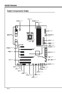
En-4 MS-7681 Manboard Quck Components Gude Back Panel, En-13 CPU, En-6 CPUFAN, En-16 DDR3, En-10 JPWR2, En-12 FV1, En-24 S Y S F A N 3 ~ 4 , En-16 JPWR1, En-12 JDLED3, En-21 JBAT1, En-22 SYSFAN2, En-16 SATA1~8, En-15 JCI1, En-15 JFP1, JFP2, En-16 TURBO1, En-23 RESET1, En-23 POWER1, En-23 JCOM1, En-1...
Page 15 - Screw Holes; screw through the manboard screw holes nto the standoffs.; Important; the chasss that may cause short crcut of the manboard.
En-5 Englsh Screw Holes When you nstall the manboard, you have to place the manboard nto the chasss n the correct drecton. The locatons of screws holes on the manboard are shown as below. Refer above pcture to nstall standoffs n the approprate locatons on chasss and then screw through the manboard s...
Page 17 - CPU & Cooler Installaton; Algnment Key
En-7 Englsh CPU & Cooler Installaton When you are nstallng the CPU, make sure the CPU has a cooler attached on the top to prevent overheatng. Meanwhle, do not forget to apply some thermal paste on CPU before nstallng the heat snk/cooler fan for better heat dsperson. Follow the steps below to nst...
Page 20 - Memory; compatble components, please vst; Memory Populaton Rule; Dual-Channel mode Populaton Rule
En-10 MS-7681 Manboard Memory These DIMM slots are used for nstallng memory modules. For more nformaton on compatble components, please vst http://www.ms.com/ndex.php?func=testreport DDR3 240-pn, 1.5V 48x2=96 pn 72x2=144 pn Memory Populaton Rule Please refer to the followng llustratons for memory po...
Page 21 - Installng Memory Modules
En-11 Englsh Installng Memory Modules The memory module has only one notch on the center and wll only fit n the rght orentaton.Insert the memory module vertcally nto the DIMM slot. Then push t n untl the golden finger on the memory module s deeply nserted n the DIMM slot. The plastc clp at each sde ...
Page 22 - Power Supply; ATX power supply, please plug your power supply along wth pn 1 & pn 13.; sure stable operaton of the manboard.
En-12 MS-7681 Manboard Power Supply ATX 24-pn Power Connector: JPWR1 Ths connector allows you to connect an ATX 24-pn power supply. To connect the ATX 24-pn power supply, make sure the plug of the power supply s nserted n the proper orentaton and the pns are algned. Then push down the power supply f...
Page 23 - Back Panel; mouse/keyboard DIN connector s for a PS/2; audo transmsson to external speakers through a coaxal cable.
En-13 Englsh Back Panel Mouse/Keyboard The standard PS/2 ® mouse/keyboard DIN connector s for a PS/2 ® mouse/keyboard. Clear CMOS Button (optonal) There s a CMOS RAM on board that has a power supply from external battery to keep the system configuraton data. Wth the CMOS RAM, the system can automatc...
Page 24 - LAN
En-14 MS-7681 Manboard USB 2.0 Port The USB (Unversal Seral Bus) port s for attachng USB devces such as keyboard, mouse, or other USB-compatble devces. Supports data transfer rate up to 480Mbt/s (H-Speed). USB 3.0 Port (optonal) USB 3.0 port s backward-compatble wth USB 2.0 devces. It supports data ...
Page 25 - Connectors; to one Seral ATA devce.; may occur durng transmsson.; Chasss Intruson Connector: JCI1; BIOS utlty and clear the record.
En-15 Englsh Connectors Seral ATA Connector: SATA1~8 (optonal) Ths connector s a hgh-speed Seral ATA nterface port. Each connector can connect to one Seral ATA devce. * The MB layout n ths figure s for reference only. SATA1~2 & SATA7~8 (6Gb/s) SATA3~6 (3Gb/s) SATA3_4 SATA1_2 SATA5_6 SATA7_8 Impo...
Page 26 - CPUFAN; The JFP1 s complant wth Intel
En-16 MS-7681 Manboard Fan Power Connectors: CPUFAN,SYSFAN1~4 The fan power connectors support system coolng fan wth +12V. When connectng the wre to the connectors, always note that the red wre s the postve and should be con- nected to the +12V; the black wre s Ground and should be connected to GND....
Page 27 - Ths connector, complant wth Intel; webste for model support lst.
En-17 Englsh Front USB 2.0 Connector: JUSB1 Ths connector, complant wth Intel ® I/O Connectvty Desgn Gude, s deal for con- nectng hgh-speed USB nterface perpherals such as USB HDD, dgtal cameras, MP3 players, prnters, modems and the lke. 11 5 V 1.VC C 3.US B0- 10.N C 5.US B0+ 7.Gro und 9.No Pin 8.Gr...
Page 29 - nterface for dgtal audo transmsson.; Seral Port Connector: JCOM1; bytes FIFOs. You can attach a seral devce.; Ths connector s provded for external audo nput.
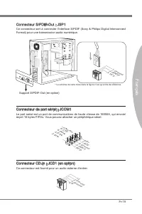
En-19 Englsh S/PDIF-Out Connector: JSP1 Ths connector s used to connect S/PDIF (Sony & Phlps Dgtal Interconnect Format) nterface for dgtal audo transmsson. 11 5 V 3.VC C 2.SP DIF 1.Gro und * The MB layout n ths figure s for reference only. S/PDIF-Out Bracket (optonal) Seral Port Connector: JCOM1...
Page 31 - Ths s reserved for connectng the ms future control card.
En-21 Englsh DLED3 Connector: JDLED3 (optonal) Ths s reserved for connectng the ms future control card. 10.N o Pin 14.C ontro l pin 8.Co ntrol pin 12.C ontro l pin 6.Gro und 4.Co ntrol pin 2.Co ntrol pin 1.5V SB 3.Co ntrol pin 5.Co ntrol pin 7.Co ntrol pin 9.Gro und 11.R eserv ed pin 13.G roun d
Page 32 - Jumpers; Clear CMOS Jumper: JBAT1; Keep Data
En-22 MS-7681 Manboard Jumpers Clear CMOS Jumper: JBAT1 There s a CMOS RAM on board wth an external battery power supply to preserve the system configuraton data. Wth the CMOS RAM, the system can automatcally boot OS every tme t s turned on. If you want to clear the system configuraton, set the jump...
Page 33 - and the system wll restore the default for next boot.; Buttons
En-23 Englsh Ths secton wll explan how to change your motherboard’s functon through the use of followng buttons. OC Gene Button: TURBO1 (optonal) Ths button s used to auto-overclock for the system. Press ths button to enable the OC Gene functon when the system s n power off state, meanwhle, the butt...
Page 35 - Slots; PCIE (Perpheral Component Interconnect Express) Slot
En-25 Englsh Slots PCIE (Perpheral Component Interconnect Express) Slot The PCIE slot supports the PCIE nterface expanson card. PCIE x16 Slot PCIE x1 Slot PCI (Perpheral Component Interconnect) Slot The PCI slot supports LAN card, SCSI card, USB card, and other add-on cards that comply wth PCI specf...
Page 36 - LED Status Indcators; Follow the nstructons below to read.
En-26 MS-7681 Manboard LED Status Indcators APS LED (P67A-GD65/ P67A-GD55/ P67A-GD53/ P67S-GD53) The APS (Actve Phase Swtchng) LED ndcate the current CPU power phase mode. Follow the nstructons below to read. : Lghts : Off CPU s n 1 phase power mode. CPU s n 2 phase power mode. CPU s n 3 phase power...
Page 37 - BIOS Setup
En-27 Englsh BIOS Setup Ths chapter provdes basc nformaton on the BIOS Setup program and allows you to configure the system for optmum use. You may need to run the Setup program when: An error message appears on the screen durng the system bootng up, and requests you to run BIOS SETUP. You want to c...
Page 38 - Control
En-28 MS-7681 Manboard Control Keyboard Mouse Descrpton <↑ ↓ > Move the cursor Select Item <Enter> Clck/ Double- clck the left but- ton Select Icon/ Feld <Esc> Clck the rght button Jumps to the Ext menu or returns to the prevous from a submenu <+> Increase the numerc value or...
Page 40 - [Yes] and clck on t to save the configuratons and ext BIOS setup utlty.
En-30 MS-7681 Manboard When enter the BIOS Setup utlty, follow the processes below for general use. Load Optmzed Defaults : Select [Settng] -> [Save & Ext] -> [Restore Defaults] and clck on t. And then the screen shows a pop-up message as below. Select [Yes] and clck on t to load the defau...
Page 46 - Software Informaton; Servce base menu : Through ths menu to lnk the MSI offically webste.
En-36 MS-7681 Manboard Software Informaton Take out the Drver/Utlty DVD that s ncluded n the manboard package, and place t nto the DVD-ROM drve. The nstallaton wll auto-run, smply clck the drver or utl- ty and follow the pop-up screen to complete the nstallaton. The Drver/Utlty DVD contans the: Drve...
Page 47 - Deutsch; Europe Verson
Deutsch P67A-GD65/P67A-GD55/P67A-GD53/P67S-GD53/P67A-SD60Sere Europe Verson
Page 48 - Spezfikatonen
De-2 MS-7681 Manboard Spezfikatonen Prozessoren Intel ® Sandy Brdge Prozessor für Sockel LGA1155 (Wetere CPU Informatonen finden Se unter http://www.ms.com/ndex. php?func=cpuform2) Base-Taktsteuerung 100 MHz Chpsatz Intel ® P67 Chpsatz Specher 4 DDR3 DIMMs unterstützen DDR3 2133*(OC)/ 1600*(OC)/ 133...
Page 49 - Anschlüsse
De-3 Deutsch Anschlüsse Hntere En-/ und Ausgänge 1 PS/2 Tastatur-/Mausanschluss 1 CMOS leeren-Taste (P67A-GD65/ P67A-GD55/ P67A-GD53/ P67S-GD53) 1 koaxaler S/PDIF-Ausgang (P67A-GD65/ P67A-GD55/ P67A-GD53/ P67S- GD53) 1 optscher S/PDIF-Ausgang (P67A-GD65/ P67A-GD55/ P67A-GD53/ P67S- GD53) 1 IEEE 1394...
Page 51 - board snd we nachfolgend gezegt.; Wchtg; Schraubenlöcher
De-5 Deutsch Schraubenlöcher Wenn Se das Manboard zu nstalleren, müssen Se das Manboard n das Chasss n der korrekten Rchtung setzen. De Standorte von Schraubenlöchern auf dem Man- board snd we nachfolgend gezegt. Verwesen Se das obge Bld, um Abstandshalter n den entsprechenden Orten auf Chasss nstal...
Page 53 - Justermarkerungen
De-7 Deutsch CPU & Kühler Enbau Wenn Se de CPU enbauen, stellen Se btte scher, dass Se auf der CPU enen Kühler anbrngen, um Überhtzung zu vermeden. Vergessen Se ncht, etwas Slzumwärmel- etpaste auf de CPU aufzutragen, bevor Se den Prozessorkühler nstalleren, um ene Abletung der Htze zu erzelen. ...
Page 56 - Specher; matonen über kompatble Bautele finden Se unter; Hnwese für den Ensatz von Spechermodulen; Btte beachten Se de folgenden Abbldungen zum Specherenbau.
De-10 MS-7681 Manboard Specher Dese DIMM-Steckplätze nehmen Arbetsspechermodule auf. De neusten Infor- matonen über kompatble Bautele finden Se unter http://www.ms.com/ndex. php?func=testreport DDR3 240-polg, 1,5V 48x2=96 Pole 72x2=144 Pole Hnwese für den Ensatz von Spechermodulen Btte beachten Se d...
Page 57 - Vorgehenswese bem Enbau von Specher Modulen
De-11 Deutsch Vorgehenswese bem Enbau von Specher Modulen De Spechermodulen haben nur ene Kerbe n der Mtte des Moduls. Se passen nur n ener Rchtung n den Sockel.Stecken Se das Arbetsspechermodul senkrecht n den DIMM-Steckplatz en. Drücken Se anschleßnd das Arbetsspechermodul nach unten, bs de Kontak...
Page 58 - Stromversorgung; Verbndung zu gewährlesten.
De-12 MS-7681 Manboard Stromversorgung ATX 24-polger Stromanschluss: JPWR1 Mt desem Anschluss verbnden Se den ATX 24-polgen Anschluss des Netztels. Achten Se be dem Verbnden des ATX 24-polgen Stromanschlusses darauf, dass der Anschluss des Netztels rchtg auf den Anschluss an der Hauptplatne ausgerch...
Page 59 - Maus/Tastatur Stecker Mn DIN st für ene PS/2; n den Werkszustand zurücksetzen
De-13 Deutsch Rücktafel Maus/Tastatur De Standard PS/2 ® Maus/Tastatur Stecker Mn DIN st für ene PS/2 ® Maus/Tastatur. CMOS leeren-Taste (optonal) Auf dem Manboard befindet sch en CMOS RAM, dass durch ene zusätzlche Battere versorgt wrd um Daten der Systemkonfiguraton zu spechern. Mt desem CMOS RAM ...
Page 61 - schluss kann en S-ATA Gerät angeschlossen werden.; Datenverlusten während der Datenübertragung führt.; Gehäusekontaktanschluss: JCI1; gerufen und de Aufzechnung gelöscht werden.
De-15 Deutsch Anschlüssen Seral ATA Anschluss: SATA1~8 (optonal) Der Anschluss st ene Hochgeschwndgketsschnttstelle der Seral ATA. Pro An- schluss kann en S-ATA Gerät angeschlossen werden. * Das MB-Layout n deser Abbldung haben nur Orenterungscharakter. SATA1~2 & SATA7~8 (6Gb/s) SATA3~6 (3Gb/s) ...
Page 62 - de Vortele der Steuerung des CPU Lüfters zu nutzen.; LEDs des Frontpanels. JFP1 erfüllt de Anforderungen des “Intel
De-16 MS-7681 Manboard Stromanschlüsse für Lüfter: CPUFAN,SYSFAN1~4 De Anschlüsse unterstützen aktve Systemlüfter mt + 12V. Wenn Se den Anschluss herstellen, sollten Se mmer darauf achten, dass der rote Draht der postve Pol st, und mt +12V verbunden werden sollte. Der schwarze Draht st der Erdkontak...
Page 63 - Deser Anschluss entsprcht den Rchtlnen des Intel; unterstützt de neue Super-Charger-Technologe
De-17 Deutsch USB 2.0 Vorderanschluss: JUSB1 Deser Anschluss entsprcht den Rchtlnen des Intel ® I/O Connectvty Desgn Gude. Er st bestens geegnet, Hochgeschwndgkets- USB- Perpheregeräte anzuschleßen, we z.B. USB Festplattenlaufwerke, Dgtalkameras, MP3-Player, Drucker, Modems und ähnlches. 11 5 V 1.VC...
Page 64 - schluss enes IEEE 1394-Gerätes ermöglcht.
De-18 MS-7681 Manboard USB 3.0 Vorderanschluss: JUSB2 (optonal) Der USB 3.0 Anschluss st abwärtskompatbel mt USB 2.0-Geräten. Unterstützt Daten- transferraten bs 5 Gbt/s (SuperSpeed). 11 5 V 5.US B3_T X3_C _DN 4.Gro und 3.US B3_R X3_D P 2.US B3_R X3_D N 1.FU SB_V CC2 10.N C 9.SB D0+ 8.SB D0- 7.Gro u...
Page 65 - tragung dgtaler Audodaten verwendet.; Sereller Anschluss: JCOM1
De-19 Deutsch S/PDIF-Ausgang: JSP1 De S/PDIF (Sony & Phlps Dgtal Interconnect Format) Schnttstelle wrd für de Über- tragung dgtaler Audodaten verwendet. 11 5 V 3.VC C 2.SP DIF 1.Gro und * Das MB-Layout n deser Abbldung haben nur Orenterungscharakter. S/PDIF-Ausgang Slotblech (optonal) Sereller A...
Page 66 - Audoanschluss des Frontpanels: JAUD1; panels. Der Anschluss entsprcht den Rchtlnen des “ Intel
De-20 MS-7681 Manboard Audoanschluss des Frontpanels: JAUD1 Deser Anschluss ermöglcht den Anschluss von Audoen und -ausgängen enes Front- panels. Der Anschluss entsprcht den Rchtlnen des “ Intel ® Front Panel I/O Connectv- ty Desgn Gude”. 1.MIC L 3.MIC R 10.H ead Phon e De tectio n 5.He ad P hone R ...
Page 68 - Steckbrücke; Halten Se sch an de Anwesungen n der Grafik, um de Daten löschen.; Halten Daten
De-22 MS-7681 Manboard Steckbrücke Steckbrücke zur CMOS- Löschung: JBAT1 Der Onboard CMOS Specher (RAM) wrd über ene zusätzlche Bettere mt Strom versorgt, um de Daten der Systemkonfiguraton zu spechern. Er ermöglcht es dem Betrebssystem, mt jedem Enschalten automatsch hochzufahren. Wenn Se de Sys- t...
Page 69 - brauch der Taste ändert.; per/ Kühler mt OC Gene Funkton aus; Tasten
De-23 Deutsch Deser Abschntt beschrebt, we man de Funktonen des Motherboards durch den Ge- brauch der Taste ändert. OC Gene Taste: TURBO1 (optonal) Dese Taste wrd zum Selbstübertaktung für das System benutzt. Drücken Se dese Taste, um der OC Gene Funkton zu ermöglchen, wenn das System m spannung- sl...
Page 71 - PCIE (Perpheral Component Interconnect Express) Steckplatz; Folge1 Folge2 Folge3 Folge4
De-25 Deutsch Steckplätze PCIE (Perpheral Component Interconnect Express) Steckplatz Der PCIE-Steckplatz unterstützt ene Erweterungskarte mt der PCIE-Schnttstelle. PCIE x16-Steckplatz PCIE x1-Steckplatz PCI (Perpheral Component Interconnect) Steckplatz Der PCI-Steckplatz kann LAN-Karten, SCSI-Karten...
Page 72 - LED Statusanzege; grad an. Lesen Se de folgenden Anwesungen.
De-26 MS-7681 Manboard LED Statusanzege APS LED (P67A-GD65/ P67A-GD55/ P67A-GD53/ P67S-GD53) Das APS (Actve Phase Swtchng) LED zegt den gegenwärtgen CPU Auslastungs- grad an. Lesen Se de folgenden Anwesungen. : Leuchtet : Aus CPU st n der Phase 1 des Power-Modus. CPU st n der Phase 2 des Power-Modus...
Page 73 - Se zum Aufruf des BIOS SETUP aufgefordert werden.; te - 5te Stelle bezechnen de Modelnummer.; Aufruf des BIOS Setups; F11 drücken um das Bootmenü zu errechen)
De-27 Deutsch BIOS Setup Deses Kaptel enthält Informatonen über das BIOS Setup und ermöglcht es Ihnen, Ihr System optmal auf Ihre Anforderungen enzustellen. Notwendgket zum Aufruf des BIOS besteht, wenn: Während des Bootvorgangs des Systems ene Fehlermeldung erschent und Se zum Aufruf des BIOS SETUP...
Page 74 - Steuertasten
De-28 MS-7681 Manboard Steuertasten Tastatur Maus Beschrebung <↑ ↓ > Bewegen Se den Cursor Auswahl enes Entrages <Enter> Klcken/ doppelt- klcken Se mt der lnken Maustaste Auswahl enes Symbols/ Feldes <Esc> Klcken Se mt der rechten Maustaste Aufruf Ext Menü oder zurück zum Hauptmenü...
Page 81 - Power Technology
De-35 Deutsch Power Technology Her können Se den Modus der Intel Dynamc Power Technologe auswählen. C1E Support Mt Hlfe von Speedstep ändert der Prozessor sene Taktrate, also de Rechenles- tung, je nach Enstellung bzw. Bedarf. Ncht alle Prozessor unterstützt Enhanced Halt Stand (C1E). OverSpeed Prot...
Page 82 - Servce-Bassmenü : Mt desem Menü können Se offizelle Websete des MSI; für bessere System Lestung zu erhalten.
De-36 MS-7681 Manboard Software-Informaton De m Manboard-Paket enthaltene DVD enthält alle notwendgen Treber. Um de Installaton automatsch laufen zu lassen, klcken Se enfach den Treber oder Utlty und folgen Se dem Pop-Up Schrm, um de Installaton durchzuführen. Der Treberge- brauchs-DVD enthält: Treb...
Page 83 - Franças
Franças P67A-GD65/P67A-GD55/P67A-GD53/P67S-GD53/P67A-SD60Séres Europe verson
Page 84 - Spécficatons
Fr-2 Carte mère MS-7681 Spécficatons Processeurs Supportés Intel ® Sandy Brdge processeurs dans le paquet LGA1155 (Pour plus d'nformaton sur le CPU, veullez vster http://www.ms.com/ndex. php?func=cpuform2) Horloge de base 100 MHz Jeu de puces Puces Intel ® P67 Mémore supportée 4 DDR3 DIMMs supporten...
Page 85 - França; Connecteurs
Fr-3 França s Connecteurs Panneau arrère 1 port claver/ sours PS/2 1 bouton d’effacement CMOS (P67A-GD65/ P67A-GD55/ P67A-GD53/ P67S- GD53) 1 S/PDIF-Out coaxal (P67A-GD65/ P67A-GD55/ P67A-GD53/ P67S-GD53) 1 S/PDIF-Out optque (P67A-GD65/ P67A-GD55/ P67A-GD53/ P67S-GD53) 1 port IEEE 1394 (P67A-GD65/ P...
Page 86 - Gude Rapde Des Composants
Fr-4 Carte mère MS-7681 Gude Rapde Des Composants Back Panel, Fr-13 CPU, Fr-6 CPUFAN, Fr-16 DDR3, Fr-10 JPWR2, Fr-12 FV1, Fr-24 S Y S F A N 3 ~ 4 , Fr-16 JPWR1, Fr-12 JDLED3, Fr-21 JBAT1, Fr-22 SYSFAN2, Fr-16 SATA1~8, Fr-15 JCI1, Fr-15 JFP1, JFP2, Fr-16 TURBO1, Fr-23 RESET1, Fr-23 POWER1, Fr-23 JCOM...
Page 87 - châsss qu entraînerat un court crcut à la carte mère.
Fr-5 França s Trous Taraudés Quand vous nstallez la carte mère, l faut déposer la carte dans le châsss en bonne poston. La stuaton des trous taraudés sont montrée dans la figure c-dessous. Veullez vous référer à la figure pour nstaller le support dans une poston approprée sur le châsss et pus de fix...
Page 89 - Installaton du CPU et son ventlateur; Clé d’algnement
Fr-7 França s Installaton du CPU et son ventlateur Quand vous nstallez le CPU, assurez-vous que le CPU sot équpé d’un ventlateur de refrodssement attaché sur le dessus pour évter la surchauffe. Méanmons, n’oublez pas d’applquer une couche d’endut thermque sur le CPU avant d’nstaller le ventla- teur ...
Page 92 - Mémore; d’nformatons sur les composants compatbles, veullez vster; Règles de populaton de la mémore; Règle de populaton en mode double-canaux; même type
Fr-10 Carte mère MS-7681 Mémore Ces slots DIMM sont destnés à nstaller les modules de mémore. Pour plus d’nformatons sur les composants compatbles, veullez vster http://www.ms.com/n- dex.php?func=testreport DDR3 240-pn, 1.5V 48x2=96 pn 72x2=144 pn Règles de populaton de la mémore Veullez vous référe...
Page 93 - Installaton des modules de mémore; du slot DIMM sur les côtés.; nséré dans le slot du DIMM.
Fr-11 França s Installaton des modules de mémore Le module de mémore possède une seule encoche en son centre et ne s’adaptera que s’l est orenté de la mqnère convenable.Insérez le module de mémore à la vertcale dans le slot du DIMM. Poussez-le en- sute jusqu’à l’extrémté dorée du module de mémore, s...
Page 94 - Connecteurs d’almentaton; Connecteur d’almentaton ATX 24-pn : JPWR1; gouplles soent algnées. Enfoncez alors la prse dans le connecteur.; tons ATX pour garantr une opératon stable de la carte mère.
Fr-12 Carte mère MS-7681 Connecteurs d’almentaton Connecteur d’almentaton ATX 24-pn : JPWR1 Ce connecteur vous permet de connecter l’almentaton ATX 24-pn. Pour cela, as- surez-vous que la prse d’almentaton est ben postonnée dans le bon sens et que les gouplles soent algnées. Enfoncez alors la prse d...
Page 95 - Le standard connecteur de sours/claver DIN de PS/2; système se réntalse automatquement.
Fr-13 França s Panneau arrère Sours/Claver Le standard connecteur de sours/claver DIN de PS/2 ® est pour une sours ou un claver de PS/2 ® . Bouton d’effacement CMOS (en opton) Il y a un CMOS RAM ntégré, qu possède un bloc d’almentaton almenté par une bat- tere externe, destné à conserver les données...
Page 97 - être relé à un apparel de sére ATA.; pourraient se produire pendant la transmission; Connecteur Châsss Intruson : JCI1
Fr-15 França s Connecteurs Connecteur Séral ATA : SATA1~8 (en opton) Ce connecteur est un port d’nterface de sére ATA haut débt. Chaque connecteur peut être relé à un apparel de sére ATA. * Le schéma de carte mère dans la figure n’est qu’à ttre de référence. SATA1~2 & SATA7~8 (6Gb/s) SATA3~6 (3G...
Page 98 - afin de contrôler le ventlateur de l’unté centrale.; trée/sorte du panneau avant Intel
Fr-16 Carte mère MS-7681 Connecteur d’almentaton du ventlateur : CPUFAN,SYSFAN1~4 Les connecteurs de courant du ventlateur supportent le ventlateur de refrodssement du système avec +12V. Lors du branchement des fils aux connecteurs, fates toujours en sorte que le fil rouge sot le fil postf devant êt...
Page 99 - panneau avant Intel; supporte la nouvelle technologe MSI Super-Charger.
Fr-17 França s Connecteur USB 2.0 avant : JUSB1 Ce connecteur est conforme au gude de concepton de la connectvté Entrée/sorte du panneau avant Intel ® , l est déal pour reler les pérphérques d’nterface USB à haut débt tels les dsques durs externes, les apparels photo numérques, les lecteurs MP3, les...
Page 101 - Format) pour une transmsson audo numérque.; Connecteur de port séral : JCOM1; reçot 16 bytes FIFOs. Vous pouvez attacher un pérphérque séral.; Ce connecteur est fournt pour un audo externe d’entrer.
Fr-19 França s Connecteur S/PDIF-Out : JSP1 Ce connecteur sert à connecter l’nterface S/PDIF (Sony & Phlps Dgtal Interconnect Format) pour une transmsson audo numérque. 11 5 V 3.VC C 2.SP DIF 1.Gro und * Le schéma de carte mère dans la figure n’est qu’à ttre de référence. Support S/PDIF-Out (en ...
Page 104 - Cavaler; Cavaler d’effacement CMOS : JBAT1; cavaler pour effacer les données.; tème est allumé cela endommagerat la carte mère.
Fr-22 Carte mère MS-7681 Cavaler Cavaler d’effacement CMOS : JBAT1 Il y a un CMOS RAM ntégré, qu possède un bloc d’almentaton almenté par une bat- tere externe, destné à conserver les données de configuraton du système. Avec le CMOS RAM, le système peut lancer automatquement le système d’explotaton ...
Page 105 - prochane ntalsaton; pour la dsspaton de la chaleur avec la foncton OC Gene; Bouton
Fr-23 França s Cette secton vous explque comment changer la foncton de votre carte mère avec ces boutons. Bouton OC Gene : TURBO1 (en opton) Ce bouton sert à auto-overclocker pour le système. Appuyez sur ce bouton pour actver la foncton OC Gene lorsque le système est au statut étent, néanmons, le bo...
Page 107 - Emplacement PCIE (Perpheral Component Interconnect Express)
Fr-25 França s Emplacements Emplacement PCIE (Perpheral Component Interconnect Express) L’emplacement PCIE supporte la carte d’extenson d’Interface PCIE. Emplacement PCIE x16 Emplacment PCIE x1 Emplacement PCI (Perpheral Component Interconnect) L’emplacement PCI supporte la carte LAN, la carte SCSI,...
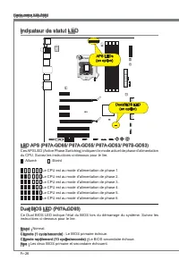
Page 108 - Indcateur de statut LED; Fxe : Les deux BIOS prmare et secondare échouent.
Fr-26 Carte mère MS-7681 Indcateur de statut LED LED APS (P67A-GD65/ P67A-GD55/ P67A-GD53/ P67S-GD53) Ces APS LED (Actve Phase Swtchng) ndquent le mode actuel de phase d'almentaton du CPU. Suvez les nstructons c-dessous pour le lre. : Allumé : Etent Le CPU est au mode d'almentaton de phase 1. Le CPU...
Page 109 - verson BIOS. Elle est généralement sous la forme :; Entrée dans le paramétrage
Fr-27 França s Réglage BIOS Ce chaptre donne des nformatons concernant le programme de réglage du BIOS et vous permet de configurer le système pour obtenr des performances d’utlsaton opt- mum. Vous aurez peut-être beson de lancer le programme de réglage lorsque : Un message d’erreur apparaît sur l’é...
Page 110 - Contrôle
Fr-28 Carte mère MS-7681 Contrôle Claver Sours Descrpton <↑ ↓ > Bouger le curseur Chosr un artcle <Entrer> Clquer/ Double- clquer le bouton gauche Chosr une cône/ un domane <Esc> Clquer le bouton drote Retourner au menu Ext ou revenr à la page précé- dente d’un sous-menu <+> ...
Page 117 - OverSpeed Protecton
Fr-35 França s OverSpeed Protecton La foncton Overspeed Protecton permet de surveller le CPU actuel ans que sa consommaton d'énerge. S elle surpasse un certan nveau, le processeur rédura automatquement sa fréquence. S vous voulez overclocker votre CPU, mettez le en [Dsabled]. Intel C-State C-state e...
Page 118 - Informaton Logcel; hatez pour actver le dspostf.; melleure performance du système.
Fr-36 Carte mère MS-7681 Informaton Logcel Sortez le DVD Plote/ Servce, qu est nclus dans la boîte de la carte mère et placez-le dans le DVD-ROM. L’nstallaton va automatquement se déclencher, clquez sur le p- lote ou sur l’utltare et suvez le pop-up de l’écran pour accomplr l’nstallaton. Le DVD de P...
Page 119 - Русский
Русский Серия P67A-GD65/P67A-GD55/P67A-GD53/P67S-GD53/P67A-SD60 Europe verson
Page 120 - Характеристики
Ru-2 MS-7681 Системная плата Характеристики Процессор Процессор Intel ® Sandy Brdge в конструктиве LGA1155 (Для получения самой новой информации о CPU, посетите сайт http://www.ms.com/ndex.php?func=cpuform2) Base Clock 100 МГц Чипсет Intel ® P67 Память 4 слота DDR3 DIMM поддерживают скорость DDR3 21...
Page 121 - Коннекторы
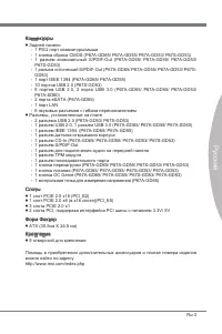
Ru-3 Русский Коннекторы Задней панели 1 PS/2 порт клавиатуры/мыши 1 кнопка сброса CMOS (P67A-GD65/ P67A-GD55/ P67A-GD53/ P67S-GD53) 1 разъем коаксиальный S/PDIF-Out (P67A-GD65/ P67A-GD55/ P67A-GD53/ P67S-GD53) 1 разъем оптический S/PDIF-Out (P67A-GD65/ P67A-GD55/ P67A-GD53/ P67S- GD53) 1 порт IEEE 1...
Page 122 - Размещение компонентов системной платы
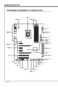
Ru-4 MS-7681 Системная плата Размещение компонентов системной платы Back Panel, Ru-13 CPU, Ru-6 CPUFAN, Ru-16 DDR3, Ru-10 JPWR2, Ru-12 FV1, Ru-24 S Y S F A N 3 ~ 4 , Ru-16 JPWR1, Ru-12 JDLED3, Ru-21 JBAT1, Ru-22 SYSFAN2, Ru-16 SATA1~8, Ru-15 JCI1, Ru-15 JFP1, JFP2, Ru-16 TURBO1, Ru-23 RESET1, Ru-23 ...
Page 123 - Внимание
Ru-5 Русский Отверстия для винтов При установке системной платы нужно вставить её в корпус в правильном направлении. Размещения отверстий для винтов показаны ниже. Следуйте указаниям выше указанно для установки держателей в правильном месте в корпусе и затем ввинтите винты через отверстия для винтов...
Page 125 - Установка процессора и вентилятора; Ключ для
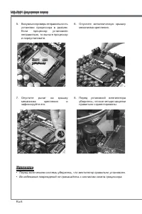
Ru-7 Русский Установка процессора и вентилятора Во избежание перегрева при работе обязательно установите вентилятор процессора. Одновременно, чтобы улучшить теплоотвод, убедитесь в том, что нанесён слой теплопроводящей пасты на процессоре перед установкой вентилятора. Следуйте данным указаниям для п...
Page 128 - Память; Правила установки модулей памяти
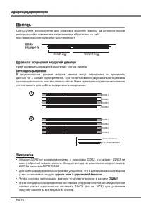
Ru-10 MS-7681 Системная плата Память Слоты DIMM используются для установки модулей памяти. За дополнительной информацией о совместимых компонентах обратитесь на сайт http://www.ms.com/ndex.php?func=testreport DDR3 240-конт, 1.5V 48x2=96 конт 72x2=144 конт Правила установки модулей памяти Ниже привед...
Page 129 - Установка модулей памяти
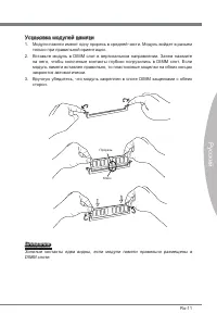
Ru-11 Русский Установка модулей памяти Модули памяти имеют одну прорезь в средней части. Модуль войдет в разьем только при правильной ориентации.Вставьте модуль в DIMM слот в вертикальном направлении. Затем нажмите на него, чтобы золоченые контакты глубоко погрузились в DIMM слот. Если модуль памяти...
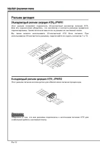
Page 130 - Разъем питания; Вы также можете использовать 20-контактный ATX блок питания. При; стабильной работы системной платы.
Ru-12 MS-7681 Системная плата Разъем питания 24-контактный разъем питания ATX: JPWR1 Этот разъем позволяет подключить 24-контактный коннектор питания ATX. Для его подключения убедитесь, что коннектор и контакты разъема правильно сориентированы. Затем плотно вставьте его в разъем на системной плате. ...
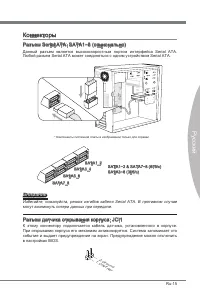
Page 133 - могут возникнуть потери данных при передаче.; Разъем датчика открывания корпуса: JCI1
Ru-15 Русский Коннекторы Разъем Seral ATA: SATA1~8 (опционально) Данный разъем является высокоскоростным портом интерфейса Seral ATA. Любой разъем Seral ATA может соединяться с одним устройством Seral ATA. * Компоненты системной платы в изображении только для справки. SATA1~2 & SATA7~8 (6Гб/с) S...
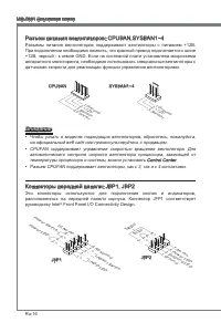
Page 134 - руководству Intel
Ru-16 MS-7681 Системная плата Разъем питания вентиляторов: CPUFAN,SYSFAN1~4 Разъемы питания вентиляторов поддерживают вентиляторы с питанием +12В. При подключении необходимо помнить, что красный провод подключается к шине +12В, черный - к земле GND. Если на системной плате установлена микросхема апп...
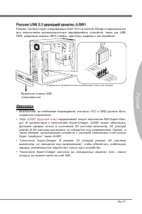
Page 135 - Разъем, соответствует спецификации Intel; Выносная планка USB; ВНИМАНИЕ, во избежание повреждений, контакты VCC и GND должны быть
Ru-17 Русский Разъем USB 2.0 передней панели: JUSB1 Разъем, соответствует спецификации Intel ® I/O Connectvty Desgn и предназначен для подключения высокоскоростных периферийных устройств, таких как USB HDD, цифровые камеры, MP3 плееры, принтеры, модемы и им подобные. 11 5 V 1.VC C 3.US B0- 10.N C 5....
Page 136 - Выносная планка USB 3.0; Выносная
Ru-18 MS-7681 Системная плата Разъем USB 3.0 передней панели: JUSB2 (опционально) Порт USB 3.0 является обратно совместимым устройством с USB 2.0. Поддержка скорости передачи данных до 5 Gbt/s (SuperSpeed). 11 5 V 5.US B3_T X3_C _DN 4.Gro und 3.US B3_R X3_D P 2.US B3_R X3_D N 1.FU SB_V CC2 10.N C 9....
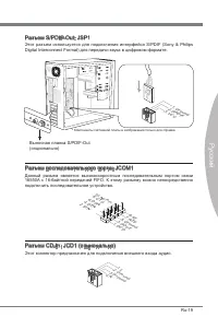
Page 137 - Dgtal Interconnect Format) для передачи звука в цифровом формате.; Разъем последовательного порта: JCOM1; подключить последовательное устройство.
Ru-19 Русский Разъем S/PDIF-Out: JSP1 Этот разъем используется для подключения интерфейса S/PDIF (Sony & Phlps Dgtal Interconnect Format) для передачи звука в цифровом формате. 11 5 V 3.VC C 2.SP DIF 1.Gro und * Компоненты системной платы в изображении только для справки. Выносная планка S/PDIF-...
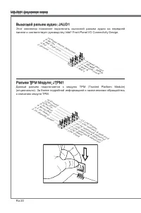
Page 138 - Выносной разъем аудио: JAUD1; панели и соответствует руководству Intel; Разъем TPM Модуля: JTPM1; Данный разъем подключается к модулю TPM (Trusted Platform Module)
Ru-20 MS-7681 Системная плата Выносной разъем аудио: JAUD1 Этот коннектор позволяет подключить выносной разъем аудио на передней панели и соответствует руководству Intel ® Front Panel I/O Connectvty Desgn. 1.MIC L 3.MIC R 10.H ead Phon e De tectio n 5.He ad P hone R 7.SE NSE _SEN D 9.He ad P hone L ...
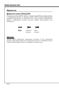
Page 140 - Перемычки; Перемычки очистки CMOS: JBAT1; CMOS при работающей системе: это повредит системную плату.
Ru-22 MS-7681 Системная плата Перемычки Перемычки очистки CMOS: JBAT1 На плате установлена CMOS память с питанием от батарейки, хранящая данные о конфигурации системы. С помощью памяти CMOS, система автоматически загружается каждый раз при включении. Если у вас возникает необходимость сбросить конфи...
Page 141 - Кнопки
Ru-23 Русский Эта глава поясняет возможности каждой из кнопок. Кнопка OC Gene: TURBO1 (опционально) Эта кнопка используется для автоматического разгона системы. Нажмите эту кнопку для включения функции OC Gene, когда система выключена. После нажатия кнопка фиксируется и будет подсвечена. Система авт...
Page 143 - Слот PCIE (Perpheral Component Interconnect Express)
Ru-25 Русский Слоты Слот PCIE (Perpheral Component Interconnect Express) Слот PCIE поддерживает карты расширения интерфейса PCIE. PCIE x16 слот PCIE x1 слот Слот PCI (Perpheral Component Interconnect) Слот PCI позволяет установить карты LAN, SCSI, USB и другие дополнительные карты расширения, которы...
Page 144 - Световые индикаторы; Информация о состоянии индикаторов приведена в таблице.
Ru-26 MS-7681 Системная плата Световые индикаторы Индикатор APS (P67A-GD65/ P67A-GD55/ P67A-GD53/ P67S- GD53) Индикаторы APS (Actve Phase Swtchng) показывают режим работы источника питания CPU. Информация о состоянии индикаторов приведена в таблице. : ВКЛЮЧЕН : ВЫКЛЮЧЕН CPU использует 1 фазу питания...
Page 146 - Контроль
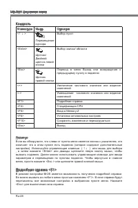
Ru-28 MS-7681 Системная плата Контроль Клавиатура Мышь Описание <↑ ↓ > Перемещение курсора Выбор пункт <Enter> Щелчок/ Двойной щелчок левой кнопки Выбор значка/ области <Esc> Щелчок правой кнопки Переход в меню Выход или возвращение к предыдущему пункту в подменю <+> Увеличен...
Page 148 - производительности системы.
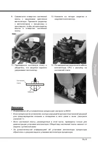
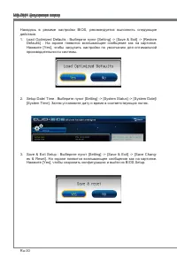
Ru-30 MS-7681 Системная плата Находясь в режиме настройки BIOS, рекомендуется выполнить следующие действия. Load Optmzed Defaults : Выберите пункт [Settng] -> [Save & Ext] -> [Restore Defaults] . На экране появится всплывающее сообщение как на картинке. Нажмите [Yes], чтобы загрузить настр...
Page 153 - C-state - это технология управления питанием, при ктивации которой
Ru-35 Русский Intel C-State C-state - это технология управления питанием, при ктивации которой значительно падает энерго потребление процессора в спящем режиме. Этот пункт доступен только при использовании CPU с поддержкой технологии C- state. Package C-State lmt Этот пункт позволяет выбрать режим C...
Page 154 - Сведения о программном обеспечении; Установите драйверы для подключения необходимых устройств.; BIOS, которые позволят улучшить производительность системы.
Ru-36 MS-7681 Системная плата Сведения о программном обеспечении Установите в привод диск Drver/Utlty (Драйверы и утилиты) из комплекта поставки системной платы. Автоматически запустится инсталляция. Нажмите на название драйвера/ утилиты и следуйте инструкциям на экране для завершения инсталляции. Д...


 MSI NX6600 Ares User Manual
 MSI NX6600-VTD256 User Manual
 MSI P45 User Manual
 MSI P55-CD53 series User Manual
-Quick-Guide-User-Manual/webp/1.webp) MSI P67A-GD55 (B3) Quick Guide User Manual
MSI P67A-GD55 (B3) Quick Guide User Manual-Quick-Guide-User-Manual/webp/1.webp) MSI P67A-GD65 (B3) Quick Guide User Manual
MSI P67A-GD65 (B3) Quick Guide User Manual-Manual-User-Manual/webp/1.webp) MSI P67A-GD80 (B3) Manual User Manual
MSI P67A-GD80 (B3) Manual User Manual MSI P240 User Manual
 MSI PH67A-C45 User Manual
 MSI PRIMO 81 User Manual
 MSI PX60-2QDi716H11 User Manual