Page 3 - Preface; Techncal Support; try the followng help resources for further gudance.; Safety Instructons; DO NOT LEAVE THIS EQUIPMENT IN AN ENVIRONMENT ABOVE 60
MS-7721 Preface Techncal Support If a problem arses wth your system and no soluton can be obtaned from the user’s manual, please contact your place of purchase or local dstrbutor. Alternatvely, please try the followng help resources for further gudance. Vst the MSI webste for techncal gude, BIOS upd...
Page 4 - CE Conformty; provsons set out n the European Drectve.; FCC-B Rado Frequency Interference Statement; cause undesred operaton.
v Preface CE Conformty Hereby, Mcro-Star Internatonal CO., LTD declares that ths devce s n complance wth the essental safety requrements and other relevant provsons set out n the European Drectve. FCC-B Rado Frequency Interference Statement Ths equpment has been tested and found to comply wth the lm...
Page 5 - Radaton Exposure Statement
v MS-7721 Preface Radaton Exposure Statement Ths equpment comples wth FCC radaton exposure lmts set forth for an uncon- trolled envronment. Ths equpment and ts antenna should be nstalled and operated wth mnmum dstance 20 cm between the radator and your body. Ths equpment and ts antenna must not be c...
Page 6 - Battery Informaton
v Preface Calforna, USA: The button cell battery may contan perchlorate materal and requres specal handlng when recycled or dsposed of n Calforna. For further nformaton please vst:http://www.dtsc.ca.gov/hazardouswaste/perchlorate/ Tawan: For better envronmental protecton, waste batteres should be co...
Page 7 - WEEE (Waste Electrcal and Electronc Equpment) Statement; ENGLISH; schlesslch an ener lokalen Altgerätesammelstelle n Ihrer Nähe.; FRANÇAIS; эти изделия в специализированные пункты приема.
v MS-7721 Preface WEEE (Waste Electrcal and Electronc Equpment) Statement ENGLISH To protect the global envronment and as an envronmentalst, MSI must re- mnd you that...Under the European Unon (“EU”) Drectve on Waste Electrcal and Electron- c Equpment, Drectve 2002/96/EC, whch takes effect on August...
Page 8 - ESPAÑOL; empresa autorzada para la recogda de estos resduos.; NEDERLANDS; lokale nzamelngspunten.; SRPSKI; vode možete vratt na lokalnm mestma za prkupljanje.; POLSKI
v Preface ESPAÑOL MSI como empresa comprometda con la proteccón del medo ambente, recomenda:Bajo la drectva 2002/96/EC de la Unón Europea en matera de desechos y/o equ- pos electróncos, con fecha de rgor desde el 13 de agosto de 2005, los productos clasficados como “eléctrcos y equpos electróncos” n...
Page 9 - TÜRKÇE; noktalarına bırakablrsnz.; ČESKY; cclo d vta. È possble portare prodott nel pù vcno punto d raccolta
x MS-7721 Preface TÜRKÇE Çevrec özellğyle blnen MSI dünyada çevrey korumak çn hatırlatır:Avrupa Brlğ (AB) Kararnames Elektrk ve Elektronk Malzeme Atığı, 2002/96/EC Kararnames altında 13 Ağustos 2005 tarhnden tbaren geçerl olmak üzere, elektrkl ve elektronk malzemeler dğer atıklar gb çöpe atılamayaca...
Page 10 - CONTENTS
x Preface CONTENTS ▍ Englsh ...................................................................................................... En-1 Manboard Specficatons ...................................................................................En-2Connectors Quck Gude .....................................
Page 13 - Englsh
Page 14 - Manboard Specficatons
En-2 MS-7721 Manboard Manboard Specficatons Processor Support AMD ® A10/A8/A6/A4-seres processors for the FM2 package Chpset AMD ® A75/ A55 chpset Memory Support 2x DDR3 DIMMs support DDR3 2133(OC)/ 1866/ 1600/ 1333/ 1066 DRAM (16GB Max) Supports Dual-Channel mode LAN Supports LAN 10/100/1000 Fast E...
Page 16 - Connectors Quck Gude
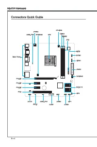
En-4 MS-7721 Manboard Connectors Quck Gude Back Panel APU CPUFAN JPWR1 SYSFAN1 SATA1~6 JFP2 JCI1 JTPM1 JCOM1 JLPT1 DIMM1 DIMM2 JFP1 JUSB3 JUSB2 JUSB1 JUSB_PW1 JBAT1 JAUD1 PCI1 PCI_E3 PCI_E2 PCI_E1 SYSFAN2 JPWR2 JUSB_PW2
Page 17 - Connectors Reference Gude
En-5 Englsh Connectors Reference Gude Port Name Port Type Page Back Panel En-6 APU FM2 APU Socket En-8 CPUFAN,SYSFAN1~2 Fan Power Connectors En-18 DIMM1~2 DDR3 Memory Slots En-13 JAUD1 Front Panel Audo Connector En-19 JBAT1 Clear CMOS Jumper En-25 JCI1 Chasss Intruson Connector En-23 JCOM1 Seral Por...
Page 18 - Back Panel Quck Gude; Important; LAN
En-6 MS-7721 Manboard Back Panel Quck Gude Mouse/Keyboard A combnaton PS/2 ® mouse/keyboard DIN connector for a PS/2 ® mouse/keyboard. USB 2.0 Port The USB 2.0 port s for attachng USB 2.0 devces such as keyboard, mouse, or other USB 2.0-compatble devces. USB 3.0 Port (FM2-A75MA-E35) USB 3.0 port s b...
Page 20 - Overheatng; Introducton to FM2 APU
En-8 MS-7721 Manboard APU (Accelerated Processng Unts) Important Overheatng Overheatng can serously damage the APU and manboard. Always make sure the coolng fans work properly to protect the APU from overheatng. Be sure to apply an even layer of thermal paste (or thermal tape) between the APU and th...
Page 21 - APU & Cooler Installaton
En-9 Englsh APU & Cooler Installaton When you are nstallng the APU, make sure the APU has a cooler attached on the top to prevent overheatng. Meanwhle, do not forget to apply some thermal paste on APU before nstallng the heat snk/cooler fan for better heat dsperson. Follow the steps below to nst...
Page 23 - Mountng Screw Holes; the computer case that may cause a short crcut of the manboard.
En-11 Englsh Mountng Screw Holes When nstallng the manboard, first nstall the necessary mountng stands requred for an manboard on the mountng plate n your computer case. If there s an I/O back plate that came wth the computer case, please replace t wth the I/O backplate that came wth the manboard pa...
Page 24 - Power Supply; hooked on the manboard’s power connector.; ply to ensure stable operaton of the manboard.
En-12 MS-7721 Manboard Power Supply JPWR1: ATX 24-pn Power Connector Ths connector allows you to connect an ATX 24-pn power supply. To connect the ATX 24-pn power supply, algn the power supply cable wth the connector and firmly press the cable nto the connector. If done correctly, the clp on the pow...
Page 25 - Memory; Dual-Channel mode Populaton Rule; (not full 16 GB) when all DIMM slots have 8GB memory modules nstalled.
En-13 Englsh Memory These DIMM slots are used for nstallng memory modules. For more nformaton on compatble components, please vst http://www.ms.com/servce/test-report DDR3 240-pn, 1.5V 48x2=96 pn 72x2=144 pn Dual-Channel mode Populaton Rule In Dual-Channel mode, the memory modules can transmt and re...
Page 26 - Installng Memory Modules
En-14 MS-7721 Manboard Installng Memory Modules Unlock the DIMM slot by pushng the mountng clps to the sde. Vertcally nsert the memory module nto the DIMM slot. The memory module has an off-center notch on the bottom that wll only allow t to fit one way nto the DIMM slot.Push the memory module deep ...
Page 27 - Expanson Slots; PCIe (Perpheral Component Interconnect Express) Slot; The PCIe slot supports the PCIe nterface expanson card.; PCI (Perpheral Component Interconnect) Slot; wth PCI specficatons.; PCI Interrupt Request Routng; Order1 Order2 Order3 Order4
En-15 Englsh Expanson Slots Ths manboard contans numerous ports for expanson cards, such as dscrete graphcs or audo cards. PCIe (Perpheral Component Interconnect Express) Slot The PCIe slot supports the PCIe nterface expanson card. PCIe 2.0 x16 Slot PCIe 2.0 x1 Slot PCI (Perpheral Component Intercon...
Page 28 - Sngle Vdeo Card Installaton; nstallaton or other specal settngs.
En-16 MS-7721 Manboard Vdeo/ Graphcs Cards If avalable, ths manboard takes advantage of the APU’s ntegrate graphcs processor, but dscrete vdeo cards can be nstalled by way of the manboard’s expanson slots. Addng on one or more dscrete vdeo cards wll sgnficantly boost the system’s graphcs performance...
Page 29 - Internal Connectors
En-17 Englsh Internal Connectors SATA1~6: Seral ATA Connector Ths connector s a hgh-speed Seral ATA nterface port. Each connector can connect to one Seral ATA devce. Seral ATA devces nclude dsk drves (HDD), sold state drves (SSD), and optcal drves (CD/ DVD/ Blu-Ray). * The MB layout n ths figure s f...
Page 31 - case. Ths connector s complant wth the Intel
En-19 Englsh JFP1, JFP2: Front Panel Connectors These connectors connect to the front panel swtches and LEDs. The JFP1 connector s complant wth the Intel ® Front Panel I/O Connectvty Desgn Gude. When nstallng the front panel connectors, please use the enclosed mConnectors to smplfy nstalla- ton. Plu...
Page 32 - securty platform manual for more detals and usages.; TPM module s optonal
En-20 MS-7721 Manboard JUSB2~3: USB 2.0 Expanson Connectors Ths connector s desgned for connectng hgh-speed USB perpherals such as USB HDDs, dgtal cameras, MP3 players, prnters, modems, and many others. 11 5 V 1.VC C 3.US B0- 10.N C 5.US B0+ 7.Gro und 9.No Pin 8.Gro und 6.US B1+ 4.US B1- 2.VC C * Th...
Page 33 - bytes FIFOs. You can attach a seral devce.
En-21 Englsh JLPT1: Parallel Port Header Ths connector s used to connect an optonal parallel port bracket. The parallel port s a standard prnter port that supports Enhanced Parallel Port (EPP) and Extended Capabltes Parallel Port (ECP) mode. 10.G roun d 14.G roun d 8.LP T_S LIN# 12.G roun d 6.PIN IT...
Page 35 - JCI1: Chasss Intruson Connector; enter the BIOS utlty and clear the record.
En-23 Englsh JCI1: Chasss Intruson Connector Ths connector connects to the chasss ntruson swtch cable. If the computer case s opened, the chasss ntruson mechansm wll be actvated. The system wll record ths ntruson and a warnng message wll flash on screen. To clear the warnng, you must enter the BIOS ...
Page 36 - Jumper; Keep USB power to
En-24 MS-7721 Manboard Jumper JUSB_PW1~2: USB power Jumper The USB ports on the rear IO panel are controled by JUSB_PW2. The JUSB1 and JUSB2 are controled by JUSB_PW1. These jumpers allow you to enable/ dsable the “wakeup from S3/S4/S5 by USB and PS/2 devce” functon. Close 1-2 Keep USB power to VCC5...
Page 37 - JBAT1: Clear CMOS Jumper; Keep Data; t wll damage the manboard.
En-25 Englsh JBAT1: Clear CMOS Jumper There s CMOS RAM onboard that s external powered from a battery located on the manboard to save system configuraton data. Wth the CMOS RAM, the system can automatcally boot nto the operatng system (OS) every tme t s turned on. If you want to clear the system con...
Page 38 - Drvers and Utltes; advantage of any specal features we provde.; Total Installer; You can also use the same method to nstall the utltes.
En-26 MS-7721 Manboard Drvers and Utltes After you nstall the operatng system you wll need to nstall drvers to maxmze the performance of the new computer you just bult. MSI manbaord comes wth a Drver Dsc. Drvers allow the computer to utlze your manboard more efficently and take advantage of any spec...
Page 39 - BIOS Setup; Enterng
En-27 Englsh BIOS Setup Clck BIOS II s developed by MSI that provdes a graphcal user nterface for settng parameters of BIOS by usng the mouse and the keybord. Wth the Clck BIOS II, users can change BIOS settngs, montor CPU temperature, select the boot devce prorty and vew system nformaton such as th...
Page 48 - Install Wndows XP Notes; Ths secton descrbes how to nstall Wndows XP wth IDE or AHCI mode.; Installng Wndows XP wth IDE Mode; prepare AHCI drvers for Wndows XP n advanced.
En-36 MS-7721 Manboard Install Wndows XP Notes Ths secton descrbes how to nstall Wndows XP wth IDE or AHCI mode. Installng Wndows XP wth IDE Mode You wll fal and encounter a blue screen whle nstallng Wndows XP, because t s not natvely supported to be nstalled n the storage devce wth AHCI mode. If yo...
Page 51 - Deutsch
Page 52 - Spezfikatonen
De-2 MS-7721 Manboard Spezfikatonen Prozessoren AMD ® A10/A8/A6/A4-Sere Prozessoren für FM2 Package Chpsatz AMD ® A75/ A55 Chpsatz Specher 2x DDR3 DIMMs unterstützen für DDR3 2133(OC)/ 1866/ 1600/ 1333/ 1066 DRAM (max. 16GB) Unterstützt de Modus Dual-Kanal LAN Unterstützt LAN 10/100/1000 Fast Ethern...
Page 53 - Steckplätze
De-3 Deutsch Steckplätze 1x PCIe 2.0 x16-Steckplatz 2x PCIe 2.0 x1-Steckplätze 1x PCI-Steckplatz Form Faktor Mcro-ATX (24,4 cm X 22,8 cm) chraubenlöcher für de Montage Schraubenlöcher für de Montage x6 Dual-Grafik Unterstützt de AMD ® Dual-Grafik Technologe Btte besuchen Se AMDs offizelle Websete, u...
Page 54 - Anschlussüberscht
De-4 MS-7721 Manboard Anschlussüberscht Rücktafel APU CPUFAN JPWR1 SYSFAN1 SATA1~6 JFP2 JCI1 JTPM1 JCOM1 JLPT1 DIMM1 DIMM2 JFP1 JUSB3 JUSB2 JUSB1 JUSB_PW1 JBAT1 JAUD1 PCI1 PCI_E3 PCI_E2 PCI_E1 SYSFAN2 JPWR2 JUSB_PW2
Page 56 - Maus/Tastatur Stecker DIN st für ene PS/2; Wchtg
De-6 MS-7721 Manboard Rücktafel-Überscht Maus/Tastatur De Standard PS/2 ® Maus/Tastatur Stecker DIN st für ene PS/2 ® Maus/Tastatur. USB 2.0 Anschluss Der USB 2.0 Anschluss dent zum drekten Anschluss von USB 2.0-Geräten, we etwa Tastatur, Maus oder weterer USB 2.0-kompatbler Geräte. USB 3.0 Anschlus...
Page 58 - Überhtzung; Erklärung zur FM2 APU; de CPU auf zut ragen, um ene Abletung der Htze zu erzelen.
De-8 MS-7721 Manboard APU (Accelerated Processng Unts) Wchtg Überhtzung Überhtzung beschädgt de APU und das System nachhaltg. Stellen Se stets ene korrekte Funktonswese des APU Kühlers scher, um de APU vor Überhtzung zu schützen. Überprüfen Se ene glechmäßge Schcht der thermschen Paste (oder ther- m...
Page 62 - Stromversorgung; Verbndung zu gewährlesten.
De-12 MS-7721 Manboard Stromversorgung JPWR1: ATX 24-polger Stromanschluss Mt desem Anschluss verbnden Se den ATX 24-polgen Anschluss des Netztels. Achten Se be dem Verbnden des ATX 24-polgen Stromanschlusses darauf, dass der Anschluss des Netztels rchtg auf den Anschluss an der Hauptplatne ausgerch...
Page 63 - tonen über kompatble Bautele finden Se unter
De-13 Deutsch Specher Dese DIMM-Steckplätze nehmen Arbetsspechermodule auf. De neusten Informa- tonen über kompatble Bautele finden Se unter http://www.ms.com/servce/test-report DDR3 240-polg, 1,5V 48x2=96 Pole 72x2=144 Pole Populatonsregeln für Dual-Kanal-Specher Im Dual-Kanal-Modus können Arbetssp...
Page 64 - Vorgehenswese bem Enbau von Specher Modulen
De-14 MS-7721 Manboard Vorgehenswese bem Enbau von Specher Modulen Öffnen Se den DIMM-Steckplatz, ndem Se de Befestgungsclps zur Sete klap- pen. Stecken Se das Spechermodul senkrecht n den DIMM-Steckplatz en. Das Spechermodul hat ene Kerbe an der Untersete, so dass es nur n ener Rchtung engesetzt we...
Page 65 - PCIe (Perpheral Component Interconnect Express) Steckplatz; Der PCIe Steckplatz unterstützt PCIe-Erweterungskarten.; PCI (Perpheral Component Interconnect) Steckplatz; Zusatzkarten aufnehmen, de mt den PCI-Spezfikatonen konform snd.; Hardware oder Software-Änderungen zu überprüfen.
De-15 Deutsch Erweterungssteckplätze Deses Motherboard enthält zahlreche Schnttstellen für Erweterungskarten, we ds- krete Grafik-oder Soundkarten. PCIe (Perpheral Component Interconnect Express) Steckplatz Der PCIe Steckplatz unterstützt PCIe-Erweterungskarten. PCIe 2.0 x16-Steckplatz PCIe 2.0 x1-S...
Page 66 - Installaton ener Grafikkarte; ener gesonderten Stromversorgung.
De-16 MS-7721 Manboard Vdeo/ Grafikkarten Fall m Prozessor ntegrert, nutzt deses Manboard den m Prozessor befindlchen Grafikprozessor. Zusätzlche Grafikkarten können aber über de auf dem Manboard verfügbaren Erweterungssteckplätze engesetzt werden um de Systemlestung zu er- höhen. Installaton ener G...
Page 67 - flachen Stecker auf dem Manboard enstecken.
De-17 Deutsch Interne Anschlüsse SATA1~6: SATA Anschlüsse Deser Anschluss basert auf der Hochgeschwndgketsschnttstelle Seral ATA (SATA). Pro Anschluss kann en Seral ATA Gerät angeschlossen werden. Zu Seral ATA Geräten gehören Festplatten (HDD), SSD Festplatten (SSD) und optsche Laufwerke (CD-/DVD-/B...
Page 69 - LEDs des Frontpanels. JFP1 erfüllt de Anforderungen des “Intel; Frontpanels. Der Anschluss entsprcht den Rchtlnen des “ Intel
De-19 Deutsch JFP1, JFP2: Frontpanel Anschlüsse Dese Anschlüsse snd für das Frontpanel. Se denen zum Anschluss der Schalter und LEDs des Frontpanels. JFP1 erfüllt de Anforderungen des “Intel ® Front Panel I/O Con- nectvty Desgn Gude”. Be der Installaton des Frontpanel-Anschlüsse, nutzen Se btte das ...
Page 70 - dem TPM Plattform Handbuch.; TPM Modul st optonal
De-20 MS-7721 Manboard JUSB2~3: USB 2.0 Erweterungsanschlüsse Deser Anschluss egnet sch für de Verbndung der Hochgeschwndgkets- USB- Pe- rpheregeräte, we z.B. USB Festplattenlaufwerke, Dgtalkameras, MP3-Player, Druck- er, Modems und ähnlches. 11 5 V 1.VC C 3.US B0- 10.N C 5.US B0+ 7.Gro und 9.No Pin...
Page 71 - JLPT1: Parallele Schnttstelle; betreben werden kann.; JCOM1: Sereller Anschluss
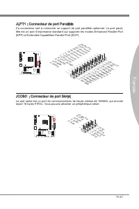
De-21 Deutsch JLPT1: Parallele Schnttstelle De Parallele Schnttstelle st ene Standard Druckerschnttstelle, de ebenso als Enhanced Parallel Port (EPP) und als Extended Capabltes Parallel Port (ECP) betreben werden kann. 10.G roun d 14.G roun d 8.LP T_S LIN# 12.G roun d 6.PIN IT# 4.ER R# 2.AF D# 24.G ...
Page 73 - JCI1: Gehäusekontaktanschluss; gerufen und de Aufzechnung gelöscht werden.
De-23 Deutsch JCI1: Gehäusekontaktanschluss Deser Anschluss wrd mt enem Kontaktschalter verbunden. Wenn das PC-Gehäuse geöffnet wrd, aktvert des den Gehäuse-Kontaktschalter und ene Warnmeldung wrd auf dem Bldschrm angezegt. Um de Warnmeldung zu löschen, muss das BIOS auf- gerufen und de Aufzechnung ...
Page 74 - Steckbrücken
De-24 MS-7721 Manboard Steckbrücken JUSB_PW1~2: USB power Jumper De USB-Anschlüsse auf der Rücksete werden von JUSB_PW2 gesteuert. De JUSB1 und JUSB2 werden durch JUSB_PW1 gesteuert. Mt deser Steckbrücke können Se de Funkton “Wakeup from S3/S4/S5 by USB and PS/2 devce” aktveren/ deaktveren. Verbndet...
Page 75 - um de Daten zu löschen.; kann dadurch beschädgt werden.
De-25 Deutsch JBAT1: Steckbrücke zur CMOS-Löschung Der Onboard CMOS Specher (RAM) wrd durch ene externe Spannungsversorgung durch ene Battere auf dem Manboard versorgt, um de Daten der Systemkonfiguraton zu spechern. Er ermöglcht es dem Betrebssystem, mt jedem Enschalten automatsch hochzufahren. Wen...
Page 76 - Treber und Denstprogramme; nutzen und profiteren Se von Besonderhet, de wr beten.; Ihren neuen Computer zu nstalleren.
De-26 MS-7721 Manboard Treber und Denstprogramme Nach der Installaton des Betrebssystems müssen Se Treber nstalleren, um de Lestung des neuen Computer, den Se gerade gebaut zu maxmeren. MSI Manbaord hat ene Treber-CD. De Treber ermöglchen es Ihnen, das Manboard effizenter zu nutzen und profiteren Se...
Page 77 - Aufruf des BIOS Setups
De-27 Deutsch BIOS Setup CLICK BIOS II wrd von MSI entwckelt, de ene grafische Benutzeroberfläche der BIOS-Enstellparameter mt Maus und Tastatur betet. Mt CLICK BIOS II können Benutzer de BIOS-Enstellungen ändern, de CPU-Tem- peratur überwachen, de Boot-rehenfolge festlegen und de Systemnformatonen ...
Page 79 - Boot-Geräte Prortätsleste
De-29 Deutsch SECURITY - Mt Hlfe deses Menüs verhndern Se Engrffe ncht autorserter Personen. Verwenden Se dese Scherhetsfunktonen, um Ihr System zu schützen. Bootgerät-Prortätleste Se können de Symbole verscheben, um de Boot-Prortät ändern. Boot-Menü Mt deser Taste können Se das Boot-Menü aufrufen. ...
Page 86 - Aktualserung BIOS mt dem Lve-Update; Klcken Se auf de Taste Lve-Update; Ncht aktualseren Se das the BIOS, wenn Ihr System gut läuft.
De-36 MS-7721 Manboard Aktualserung BIOS mt dem Lve-Update Deser Abschntt erklärt, we Se das BIOS mt Hlfe des Lve-Update-Programms aktualseren können, noch das Betrebssystem gestartet wurde. Be ener bestehenden Internetverbndung kann Lve-Update das BIOS selbstständg aktualseren. Um das BIOS mt dem L...
Page 87 - Wndows XP mt IDE-Modus nstalleren; raus entsprechende AHCI-Treber für Wndows XP vor.
De-37 Deutsch Hnwese zur Wndows XP-Installaton Deser Abschntt beschrebt, we Se Wndows XP mt IDE- oder AHCI-Modus nstal- leren. Wndows XP mt IDE-Modus nstalleren De Wndows XP-Installaton schlägt fehl, en blauer Bldschrm wrd angezegt, da Spechergeräte m AHCI-Modus ncht natv unterstützt werden. Falls S...
Page 89 - Franças
Page 90 - Spécficatons
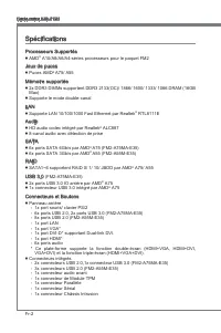
Fr-2 Carte mère MS-7721 Spécficatons Processeurs Supportés AMD ® A10/A8/A6/A4-séres processeurs pour le paquet FM2 Jeux de puces Puces AMD ® A75/ A55 Mémore supportée 2x DDR3 DIMMs supportent DDR3 2133(OC)/ 1866/ 1600/ 1333/ 1066 DRAM (16GB Max) Supporte le mode double-canal LAN Supporte LAN 10/100/...
Page 91 - França; Emplacements
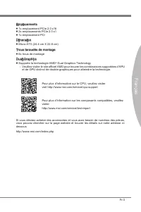
Fr-3 França s Emplacements 1x emplacement PCIe 2.0 x16 2x emplacements PCIe 2.0 x1 1x emplacement PCI Dmenson Mcro-ATX (24.4 cm X 22.8 cm) Trous taraudés de montage 6x trous de montage Dual-Graphcs Supporte la technologe AMD ® Dual Graphcs Technology Veullez vster le ste officel AMD pour trouver les...
Page 92 - Gude Rapde Des Connecteurs
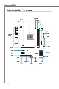
Fr-4 Carte mère MS-7721 Gude Rapde Des Connecteurs Panneau arrère APU CPUFAN JPWR1 SYSFAN1 SATA1~6 JFP2 JCI1 JTPM1 JCOM1 JLPT1 DIMM1 DIMM2 JFP1 JUSB3 JUSB2 JUSB1 JUSB_PW1 JBAT1 JAUD1 PCI1 PCI_E3 PCI_E2 PCI_E1 SYSFAN2 JPWR2 JUSB_PW2
Page 94 - Gude rapde du panneau arrère; pour une sours ou un claver PS/2
Fr-6 Carte mère MS-7721 Gude rapde du panneau arrère Sours/Claver Connecteur sours/ claver DIN de PS/2 ® pour une sours ou un claver PS/2 ® . Port USB 2.0 Le port USB 2.0 sert à brancher des pérphérques USB 2.0 tels que le claver, la sours, ou d’autres pérphérques compatbles USB 2.0. Port USB 3.0 (F...
Page 96 - Processeur APU (Accelerated Processng Unts); Surchauffe; Introducton du FM2 APU; pour amélorer la dsspaton de chaleur.
Fr-8 Carte mère MS-7721 Processeur APU (Accelerated Processng Unts) Important Surchauffe La surchauffe endommage séreusement le processeur et le système. Assurez-vous toujours que le système de refrodssement fonctonne correctement pour protéger le processeur de la surchauffe. Assurez-vous d’applquer...
Page 97 - Installaton d'APU et son ventlateur
Fr-9 França s Installaton d'APU et son ventlateur Quand vous nstallez l'APU, assurez-vous que l'APU est doté d'un système de refrodssement pour prévenr le surchauffe. En plus, n’oublez pas d’applquer une couche d’endut thermque sur l'APU avant d’nstaller le ventlateur pour amélorer la dsspaton de ch...
Page 99 - référer au manuel de votre boîter ordnateur.; boîte ordnateur qu entraînerat un court crcut à la carte mère.
Fr-11 França s Trous Taraudés de Montage Avant d’nstaller votre carte mère, l faut d’abord nstaller les socles de montage néce sares sur le plateau de montage du boîter de l’ordnateur. S la boîter de l’ordnateur est accompagnée par un panneau Entrée/ Sorte arrère, veullez utlser celu c plutôt que ce...
Page 100 - Connecteurs d’almentaton; JPWR1 : Connecteur d’almentaton ATX 24-pn; le connecteur d’almentaton de la carte mère.; tons ATX afin garantr une opératon stable de la carte mère.
Fr-12 Carte mère MS-7721 Connecteurs d’almentaton JPWR1 : Connecteur d’almentaton ATX 24-pn Ce connecteur vous permet de reler une almentaton ATX 24-pn. Pour cela, algnez le câble d’almentaton avec le connecteur et appuyez fermement le câble dans le con- necteur. S cec est ben fat, la pnce sur le câ...
Page 101 - Règle de populaton en mode double-canal; pour connaître les règles de populaton en mode de double-canal.; avec des modules de mémore de 8GB.
Fr-13 França s Mémore Ces emplacements DIMM sont destnés à nstaller les modules de mémore. Pour plus d’nformatons sur les composants compatbles, veullez vster http://www.ms.com/ser- vce/test-report DDR3 240-pn, 1.5V 48x2=96 pn 72x2=144 pn Règle de populaton en mode double-canal En mode de double-can...
Page 102 - Installaton des modules de mémore; pnces de l’emplacement DIMM sur les côtés.
Fr-14 Carte mère MS-7721 Installaton des modules de mémore Déveroullez l’emplacement DIMM en repoussant les pnces de montage sur le côté. Insérez vertcalement le module de mémore dans l’emplacement DIMM. Le module de mémore possède une seule encoche en son centre sur le bas et ne s’adaptera que s’l ...
Page 103 - Emplacement PCIe (Perpheral Component Interconnect Express)
Fr-15 França s Emplacements d’extenson Cette carte mère content de nombreux ports pour les cartes d’extenson, tels que les cartes graphques ou les cartes audo. Emplacement PCIe (Perpheral Component Interconnect Express) L’emplacement PCIe supporte la carte d’extenson d’Interface PCIe. Emplacement PC...
Page 104 - Cartes Vdéo/ Graphcs; Installaton de smple carte vdéo; port à l’nstallatons des plotes ou d’autres réglages spécfiques.
Fr-16 Carte mère MS-7721 Cartes Vdéo/ Graphcs La carte mère peut utlser le graphque ntégré au processeur, mas peut également utlser une carte vdéo dstncte nstallée sur un port d’extenson de la carte mère. Une carte vdéo addtonnelle peut amélorer fortement la performance graphque du sys- tème. Pour u...
Page 107 - Intel; nectés au JFP1 à l’orgne.; JAUD1 : Connecteur audo panneau avant
Fr-19 França s JFP1, JFP2 : Connecteur panneau avant Ces connecteurs se connectent aux nterrupteurs et LEDs du panneau avant. Le JFP1 est conforme au gude de concepton de la connectvté Entrée/sorte du panneau avant Intel ® . Lors d’nstallaton des connecteurs du panneau avant, veullez utlser les mCon...
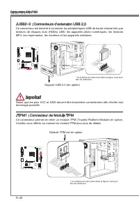
Page 108 - Veullez vous référer au manuel du module TPM pour plus de détals.; Module TPM est en opton
Fr-20 Carte mère MS-7721 JUSB2~3 : Connecteurs d’extenson USB 2.0 Ce connecteur est destné à connecter les pérphérques USB de haute-vtesse tels que lecteurs de dsques durs (HDDs) USB, les apparels photo numérques, les lecteurs MP3, les mprmantes, les modems et les apparels smlares. 11 5 V 1.VC C 3.U...
Page 109 - JLPT1 : Connecteur de port Parallèle; reçot 16 bytes FIFOs. Vous pouvez attacher un pérphérque séral.
Fr-21 França s JLPT1 : Connecteur de port Parallèle Ce connecteur sert à connecter un support de port parallèle optonnel. Le port paral- lèle est un port d’mprmante standard qu supporte les modes Enhanced Parallel Port (EPP) et Extended Capabltes Parallel Port (ECP). 10.G roun d 14.G roun d 8.LP T_S...
Page 111 - JCI1 : Connecteur Châsss Intruson
Fr-23 França s JCI1 : Connecteur Châsss Intruson Ce connecteur est connecté à un câble châsss ntruson swtch. S le châsss est ouvert, le swtch en nformera le système, qu enregstera ce statut et affichera un écran d’alerte. Pour effacer ce message d’alerte, vous devez entrer dans le BIOS et désac- tve...
Page 112 - Cavaler
Fr-24 Carte mère MS-7721 Cavaler JUSB_PW1~2 : Cavalers d’almentaton USB Les ports USB sur le panneau IO arrère sont contrôlés par JUSB_PW2. Les JUSB1 et JUSB2 sont contrôlés par JUSB_PW1. Ces cavalers vous permettent d’actver/ désac- tver la foncton “Réveller du S3/S4/S5 par pérphérque USB et PS/2”....
Page 113 - JBAT1 : Cavaler d’effacement CMOS; cavaler pour effacer CMOS RAM.; est allumé cela endommagerat la carte mère.
Fr-25 França s JBAT1 : Cavaler d’effacement CMOS Il y a un CMOS RAM ntégré, qu possède un bloc d’almentaton almenté par une bat- tere externe, destné à conserver les données de configuraton du système. Avec le CMOS RAM, le système peut lancer automatquement le système d’explotaton chaque fos qu’l es...
Page 114 - Plotes et Utltares; développer les fonctons fournes.; Installaton totale; Vous pouvez nstaller les utltares de la même façon.
Fr-26 Carte mère MS-7721 Plotes et Utltares Après l’nstallaton du système d’explotaton, l faut nstaller des plotes pour maxmser la performance de l’ordnateur. La carte mère MSI est doté d’un dsque plotes. Ces plotes permettent l’ordnateur d’employer la carte mère plus efficacement et de ben développ...
Page 115 - Entrée
Fr-27 França s Réglage BIOS CLICK BIOS II est développé par MSI qu fournt une nterface graphque d'utlsateur pour régler les paramètres de BIOS a l'ade de la sours et le claver.Avec CLICK BIOS II, vous pouvez modfier les réglages BIOS, surveller la température du CPU, chosr la prorté de pérphérque dé...
Page 117 - Opératon
Fr-29 França s Opératon CLICK BIOS II vous permet de contrôler les réglages BIOS avec la sours et le claver. La lste c-dessous décrt les opératons des touches raccourcs et de la sours. Touches Sours Descrpton <↑↓→← > Bouger le curseur Chosr un artcle <Enter> Clquer/ Double-clquer le bout...
Page 123 - Mettre à jour le BIOS avec Lve Update
Fr-35 França s Mettre à jour le BIOS avec Lve Update Cette parte vous explque comment mettre à jour le BIOS en utlsant l'utltare Lve Update avant d'entrer dans le système d'explotaton. Lve Update mettra à jour le BIOS automatquement lorsqu'l est connecté à l'Internet. Pour mettre à jour le BIOS avec...
Page 124 - Remarques d’Installon Wndows XP; Installer Wndows XP avec IDE Mode; mode, veullez préparer les plotes AHCI pour Wndows XP avancé.
Fr-36 Carte mère MS-7721 Remarques d’Installon Wndows XP Cette parte explque comment nstaller Wndows XP avec IDE ou AHCI mode. Installer Wndows XP avec IDE Mode Vous allez échouer et verrez un écran bleu lors de l’nstallaton Wndows XP, parce qu’l n’est pas prévu de l’nstaller dans le pérphérque de s...
Page 125 - Installer le système d’explotaton Wndows XP :
Fr-37 França s Installer le système d’explotaton Wndows XP : Veullez suvre les étapes suvantes : Accédez au BIOS, configurez SATA Mode au AHCI mode, sauvegardez, quttez et redémarrez-le.Assurez la bonne connecton du lecteur de dsquette USB à l'ordnateur.Installer Wndows XP. Lorsqu'l apparat sur l'éc...
Page 127 - Русский
Page 128 - Характеристики системной платы
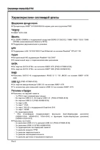
Ru-2 Системная плата MS-7721 Характеристики системной платы Поддержка процессоров Процессоры AMD ® A10/A8/A6/A4-серии для конструктива FM2 Чипсет AMD ® A75/ A55 Память 2x DDR3 DIMMs с поддержкой модулей DDR3 2133(OC)/ 1866/ 1600/ 1333/ 1066 DRAM (максимальная емкость16ГБ) Поддержка двухканального ре...
Page 129 - Слоты
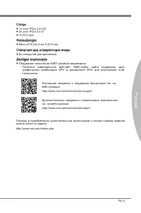
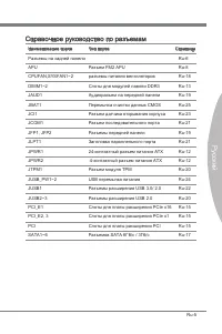
Ru-3 Русский - - - Последние сведения о поддержке процессора см. на веб-страницеhttp://www.ms.com/servce/cpu-support Дополнительные сведения о совместимых компонентах см. на веб-странице http://www.ms.com/servce/test-report Помощь в приобретении дополнительных аксессуаров и поиске номера изделия мож...
Page 130 - Краткое руководство по разъемам
Ru-4 Системная плата MS-7721 Краткое руководство по разъемам Назад панель APU CPUFAN JPWR1 SYSFAN1 SATA1~6 JFP2 JCI1 JTPM1 JCOM1 JLPT1 DIMM1 DIMM2 JFP1 JUSB3 JUSB2 JUSB1 JUSB_PW1 JBAT1 JAUD1 PCI1 PCI_E3 PCI_E2 PCI_E1 SYSFAN2 JPWR2 JUSB_PW2
Page 132 - Краткое руководство по работе с задней панелью; Разъем мыши/клавиатуры; Вниимание
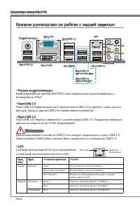
Ru-6 Системная плата MS-7721 Краткое руководство по работе с задней панелью Разъем мыши/клавиатуры Комбинированный разъем DIN PS/2 ® для подключения мыши/клавиатуры с интерфейсом PS/2 ® . Порт USB 2.0 Порт USB 2.0 предназначен для подключения USB 2.0-устройств, таких как кла- виатура, мышь и другие ...
Page 133 - Внимание
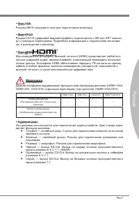
Ru-7 Русский Порт VGA Разъем DB15 гнездового типа для подключения монитора. Порт DVI-D Разъем DVI-D (цифровой видеоинтерфейс) подключается к ЖК или ЭЛТ монито- ру с помощью переходника. Подробную информацию о подключении монитора см. в руководстве к монитору. Порт HDMI Мультимедийный интерфейс высок...
Page 134 - Перегрев; Процессор FM2; что нанесен слой термопасты на процессоре.
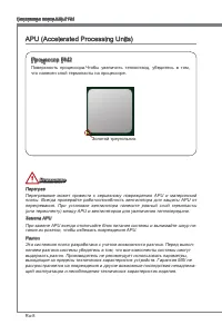
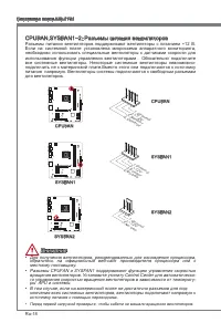
Ru-8 Системная плата MS-7721 APU (Accelerated Processng Unts) Внимание Перегрев Перегревание может привести к серьезному повреждению APU и материнской платы. Всегда проверяйте работоспособность вентилятора для защиты APU от перегревания. При установке вентилятора нанесите ровный слой термопасты (или...
Page 135 - Установка APU и вентилятора
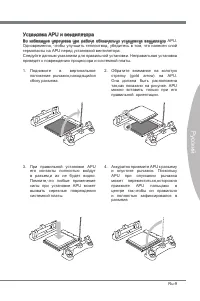
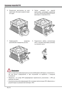
Ru-9 Русский Установка APU и вентилятора Во избежание перегрева при работе обязательно установите вентилятор APU. Одновременно, чтобы улучшить теплоотвод, убедитесь в том, что нанесен слой термопасты на APU перед установкой вентилятора. Следуйте данным указаниям для правильной установки. Неправильна...
Page 137 - привести к короткому замыканию материнской платы.
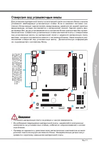
Ru-11 Русский Отверстия под установочные винты Для установки материнской платы на монтажной плате системного блока сначала установите необходимые установочные стойки. Если в комплект поставки сис- темного блока входит задняя панель ввода-вывода, замените ее задней панелью ввода-вывода, которая поста...
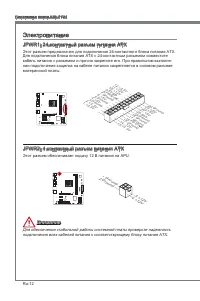
Page 138 - Электропитание; Этот разъем обеспечивает подачу 12 В питания на APU.
Ru-12 Системная плата MS-7721 Электропитание JPWR1: 24-контактный разъем питания ATX Этот разъем предназначен для подключения 24-контактного блока питания ATX. Для подключения блока питания ATX с 24-контактным разъемом совместите кабель питания с разъемом и прочно закрепите его. При правильном выпол...
Page 139 - Модули памяти; Правила заполнения гнезд при использовании двухканального
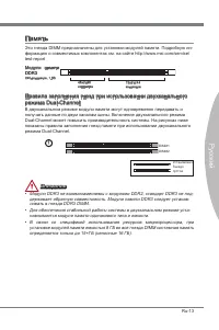
Ru-13 Русский Память Эти гнезда DIMM предназначены для установки модулей памяти. Подробную ин- формацию о совместимых компонентах см. на сайте http://www.ms.com/servce/ test-report Модули памяти DDR3 240-контактов, 1.5В 48x2=96 контактов 72x2=144 контактов Правила заполнения гнезд при использовании ...
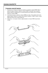
Page 140 - Установка модулей памяти; кально вставьте модуль памяти в гнездо DIMM. В нижней части модуля
Ru-14 Системная плата MS-7721 Установка модулей памяти Отодвиньте в сторону клеммные зажимы и откройте гнездо DIMM. Верти- кально вставьте модуль памяти в гнездо DIMM. В нижней части модуля памяти имеется смещенная от центра выемка для правильной установки модуля в гнездо DIMM.Установите модуль памя...
Page 141 - Слот PCIe (Perpheral Component Interconnect Express)
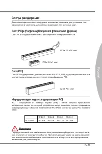
Ru-15 Русский Слоты расширения Данная материнская плата содержит множество разъемов для установки плат расширения в частности, дискретных видеокарт или звуковых карт. Слот PCIe (Perpheral Component Interconnect Express) Слот PCIe поддерживает платы расширения с интерфейсом PCIe. PCIe 2.0 x16 слот PC...
Page 142 - Установка одной видеокарты
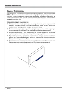
Ru-16 Системная плата MS-7721 Видео/ Видеокарты По умолчанию, данная плата использует графическое ядро интегрированное в CPU, но Вы так же можете значительно повысит графическую производительность системы, путем добавление одной или нескольких дискретных видеокарт в слоты расширения. Для лучшей совм...
Page 143 - руководствах к соответствующим устройствам.
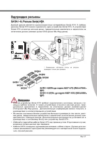
Ru-17 Русский Внутренние разъемы SATA1~6: Разъем Seral ATA Данный разъем является высокоскоростным интерфейсом Seral ATA. К любому разъему Seral ATA можно подключить одно устройство Seral ATA. К устройствам Seral ATA относятся жесткие диски, твердотельные накопители и накопители на оптических дисках...
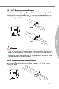
Page 145 - разъемы к материнской плате.; надписи на разъемах.; JAUD1: Аудиоразъем на передней панели; системного блока. Этот разъем соответствует стандарту Intel
Ru-19 Русский JFP1, JFP2: Разъемы передней панели Эти разъемы служат для подключения кнопок и светодиодных индикаторов, рас- положенных на передней панели. Разъем JFP1 соответствует стандартам Intel ® Front Panel I/O Connectvty Desgn. При установке разъемов передней панели для удобства используются ...
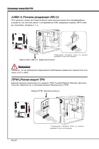
Page 146 - тельные сведения см. в описании модуля безопасности ТРМ.
Ru-20 Системная плата MS-7721 JUSB2~3: Разъемы расширения USB 2.0 Этот разъем служит для подключения таких высокоскоростных периферийных устройств, как жесткие диски с интерфейсом USB, цифровые камеры, МРЗ плее- ры, принтеры, модемы и т. д. 11 5 V 1.VC C 3.US B0- 10.N C 5.US B0+ 7.Gro und 9.No Pin 8...
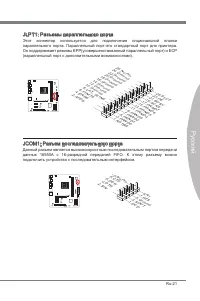
Page 147 - JLPT1: Разъемы параллельного порта; данных 16550А с 16-разрядной передачей FIFO. К этому разъему можно
Ru-21 Русский JLPT1: Разъемы параллельного порта Этот коннектор используется для подключения опциональной планки параллельного порта. Параллельный порт-это стандартный порт для принтера. Он поддерживает режимы EPP(усовершенствованный параллельный порт) и ECP (параллельный порт с дополнительными возм...
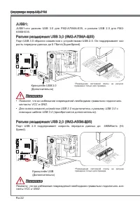
Page 148 - Кронштейн USB
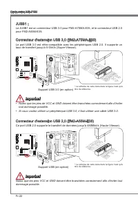
Ru-22 Системная плата MS-7721 JUSB1: JUSB1-это разъем USB 3.0 для FM2-A75MA-E35, и разъем USB 2.0 для FM2- A55M-E35. Разъем расширения USB 3.0 (FM2-A75MA-E35) Порт USB 3.0 обратно совместим с устройствами USB 2.0. Он поддерживает ско- рость передачи данных до 5 Гбит/с(SuperSpeed). 11 5 V 5.US B3_T X...
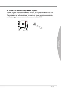
Page 149 - JCI1: Разъем датчика открывания корпуса; необходимо удалить записанное событие в настройках BIOS.
Ru-23 Русский JCI1: Разъем датчика открывания корпуса К этому разъему подключается кабель датчика, установленного в корпусе. Этот датчик срабатывает при вскрытии системного блока. Система запоминает это событие и выдает предупреждение на экран. Для отключения предупреждения необходимо удалить записа...
Page 150 - Перемычки
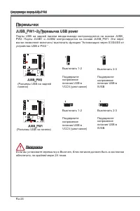
Ru-24 Системная плата MS-7721 Перемычки JUSB_PW1~2: Перемычка USB power Порты USB на задней панели ввода-вывода контролируются на основе JUSB_ PW2. Порты JUSB1 и JUSB2 контролируются на основе JUSB_PW1. Эти пере- мычки позволяют включать/ выключать функцию “Активизация через S3/S4/S5 от устройства U...
Page 151 - JBAT1: Перемычка очистки данных CMOS; Сохранение; ринскую плату из строя.
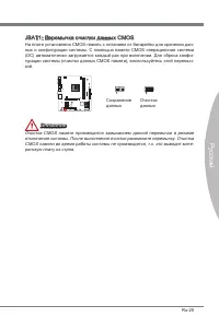
Ru-25 Русский JBAT1: Перемычка очистки данных CMOS На плате установлена CMOS-память с питанием от батарейки для хранения дан- ных о конфигурации системы. С помощью памяти CMOS операционная система (ОС) автоматически загружается каждый раз при включении. Для сброса конфи- гурации системы (очистки дан...
Page 152 - Драйверы и утилиты; полезные и креативные утилиты.; Утилита Total Installer; утилит на своем компьютере следуйте приведенным ниже указаниям.
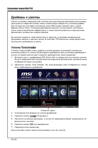
Ru-26 Системная плата MS-7721 Драйверы и утилиты После установки операционной системы для достижения максимальной произво- дительности собранного вами нового компьютера требуется установка драйве- ров. В комплект поставки системной платы MSI входит компакт-диск с драй- верами (Drver Dsc). Установка ...
Page 153 - Выполняется вход
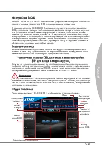
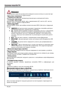
Ru-27 Русский Настройка BIOS Утилита CLICK BIOS II от MSI обеспечивает графический интерфейс пользовате- ля для установки параметров BIOS с помощи мыши и клавиатуры.С помощью утилиты CLICK BIOS II пользователи смогут изменять параметры BIOS, следить за температурой процессора, выбирать приоритетност...
Page 155 - Работа
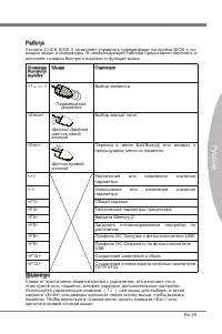
Ru-29 Русский Работа Утилита CLICK BIOS II позволяет управлять параметрами настройки BIOS с по- мощью мыши и клавиатуры. В нижеследующей таблице представлен перечень и описание «клавиш быстрого вызова» и функций мыши. Клавиша быстрого вызова Mыши Описание <↑↓→← > Перемещение указателя Выбор эл...
Page 161 - Обновление BIOS с помощью модуля Lve Update; Для обновления BIOS с помощью модуля Lve Update:
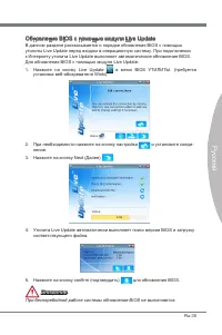
Ru-35 Русский Обновление BIOS с помощью модуля Lve Update В данном разделе рассказывается о порядке обновления BIOS с помощью утилиты Lve Update перед входом в операционную систему. При подключении к Интернету утилита Lve Update выполняет автоматическое обновление BIOS. Для обновления BIOS с помощью...
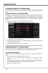
Page 162 - Установка Wndows XP Примечания; Установка Wndows XP с режимом IDE; подготовьте пожалуйста, драйвера AHCI для Wndows XP в развитых.
Ru-36 Системная плата MS-7721 Установка Wndows XP Примечания В этом разделе описывается порядок установки Wndows XP с режимами IDE или AHCI. Установка Wndows XP с режимом IDE В процессе установки Wndows XP возникает ошибка и появляется голубой экран,т. к. установка этой операционной системы не подде...
Page 163 - Установка операционной системы Wndows XP:
Ru-37 Русский Установка операционной системы Wndows XP: Пожалуйста, следуйте ниже шагов: Доступ к BIOS, установите режим SATA AHCI в режиме сохранения, выхода и перезагрузки.Убедитесь, что диск USB дисковод подключается к компьютеру.Запустите установку Wndows XP. При установке Wndows экране появляет...


-User-Manual/webp/1.webp) MSI MS-7226 (V1.X) User Manual
MSI MS-7226 (V1.X) User Manual MSI MS-7345 User Manual
 MSI MS-7512 User Manual
-Specifications/webp/1.webp) MSI MS-7521 (v2.X) User Manual
MSI MS-7521 (v2.X) User Manual MSI MS-7522 User Manual
 MSI MS-9856 User Manual
 MSI MS-S0031 User Manual
 MSI N210-MD1G/D3 User Manual
 MSI N460GTX HAWK User Manual
 MSI N620GT-MD1GD3/LP User Manual
 MSI NF725GM-P31 User Manual
 MSI NF750-G55 User Manual