Page 2 - Copyright Notice
ii Preface MS-7680 Preface Preface MS-7680 Preface Copyright Notice The material in this document is the intellectual property of MICRO-STAR INTERNA- TIONAL. We take every care in the preparation of this document, but no guarantee is given as to the correctness of its contents. Our products are unde...
Page 3 - Safety Instructions
Preface MS-7680 Preface iii Preface MS-7680 Preface Safety Instructions Always read the safety instructions carefully.Keep this User’s Manual for future reference.Keep this equipment away from humidity.Lay this equipment on a reliable flat surface before setting it up.The openings on the enclosure a...
Page 4 - FCC-B Radio Frequency Interference Statement
iv Preface MS-7680 Preface Preface MS-7680 Preface FCC-B Radio Frequency Interference Statement This equipment has been tested and found to comply with the limits for a Class B digi- tal device, pursuant to Part 15 of the FCC Rules. These limits are designed to provide reasonable protection against ...
Page 5 - Preface; Preface; Preface; WEEE (Waste Electrical and Electronic Equipment) Statement; ENGLISH; эти изделия в специализированные пункты приема.
Preface MS-7680 Preface v Preface MS-7680 Preface WEEE (Waste Electrical and Electronic Equipment) Statement ENGLISH To protect the global environment and as an environmentalist, MSI must remind you that...Under the European Union (“EU”) Directive on Waste Electrical and Elec- tronic Equipment, Dire...
Page 6 - ESPAÑOL; empresa autorizada para la recogida de estos residuos.; NEDERLANDS; lokale inzamelingspunten.; SRPSKI; vode možete vratiti na lokalnim mestima za prikupljanje.; POLSKI
vi Preface MS-7680 Preface Preface MS-7680 Preface ESPAÑOL MSI como empresa comprometida con la protección del medio ambiente, recomienda:Bajo la directiva 2002/96/EC de la Unión Europea en materia de desechos y/o equi- pos electrónicos, con fecha de rigor desde el 13 de agosto de 2005, los producto...
Page 7 - vii; TÜRKÇE; noktalarına bırakabilirsiniz.; ČESKY
Preface MS-7680 Preface vii Preface MS-7680 Preface TÜRKÇE Çevreci özelliğiyle bilinen MSI dünyada çevreyi korumak için hatırlatır:Avrupa Birliği (AB) Kararnamesi Elektrik ve Elektronik Malzeme Atığı, 2002/96/EC Kararnamesi altında 13 Ağustos 2005 tarihinden itibaren geçerli olmak üzere, elektrikli ...
Page 8 - Contents
viii Preface MS-7680 Preface Preface MS-7680 Preface Contents Copyright Notice ............................................................................................ iiTrademarks .................................................................................................... iiRevision His...
Page 9 - ix
Preface MS-7680 Preface ix Preface MS-7680 Preface Français ..................................................................................................... Fr-1 Spécifications ......................................................................................................Fr-2Guide Rapide...
Page 11 - English; Series; Europe version
English H61MU-E35/ H61M-E33/H61M-E23/H61M-P33 Series Europe version
Page 13 - Slots
MS-7680 Mainboard English En-3 MS-7680 Mainboard English * If you need to purchase accessories and request the part numbers, you could search the product web page and find details on our web address http://www.msi.com/index. php On-Board 3 USB 2.0 connectors (H61MU-E35/ H61M-E33/ H61M-E23)/ 1 USB 2....
Page 15 - Important
MS-7680 Mainboard English En-5 MS-7680 Mainboard English Screw Holes When you install the mainboard, you have to place the mainboard into the chassis in the correct direction. The locations of screws holes on the mainboard are shown as below. Refer above picture to install standoffs in the appropria...
Page 17 - CPU & Cooler Installation; Alignment Key
MS-7680 Mainboard English En-7 MS-7680 Mainboard English CPU & Cooler Installation When you are installing the CPU, make sure the CPU has a cooler attached on the top to prevent overheating. Meanwhile, do not forget to apply some thermal paste on CPU before installing the heat sink/cooler fan fo...
Page 20 - compatible components, please visit
En-10 MS-7680 Mainboard English MS-7680 Mainboard English Memory These DIMM slots are used for installing memory modules. For more information on compatible components, please visit http://www.msi.com/service/test-report DDR3 240-pin, 1.5V 48x2=96 pin 72x2=144 pin Dual-Channel mode Population Rule I...
Page 21 - Installing Memory Modules
MS-7680 Mainboard English En-11 MS-7680 Mainboard English Installing Memory Modules The memory module has only one notch on the center and will only fit in the right orientation.Insert the memory module vertically into the DIMM slot. Then push it in until the golden finger on the memory module is de...
Page 22 - This connector is used to provide the power output to the CPU.; sure stable operation of the mainboard.
En-12 MS-7680 Mainboard English MS-7680 Mainboard English Power Supply ATX 24-pin Power Connector: JPWR1 This connector allows you to connect an ATX 24-pin power supply. To connect the ATX 24-pin power supply, make sure the plug of the power supply is inserted in the proper orientation and the pins ...
Page 23 - mouse/keyboard DIN connector is for a PS/2; VGA Port; integrated graphics chip, these display ports will have no effect.
MS-7680 Mainboard English En-13 MS-7680 Mainboard English Back Panel Mouse/Keyboard The standard PS/2 ® mouse/keyboard DIN connector is for a PS/2 ® mouse/keyboard. USB 2.0 Port The USB 2.0 port is for attaching USB devices such as keyboard, mouse, or other USB- compatible devices. USB 3.0 Port (opt...
Page 24 - LAN; effect, the 7th and 8th channels must be output from front panel.
En-14 MS-7680 Mainboard English MS-7680 Mainboard English LAN The standard RJ-45 LAN jack is for connection to the Local Area Network (LAN). You can connect a network cable to it. LED Color LED State Condition Left Yellow Off LAN link is not established. On(Steady state) LAN link is established. On(...
Page 25 - to one Serial ATA device.; may occur during transmission.
MS-7680 Mainboard English En-15 MS-7680 Mainboard English Connectors Serial ATA Connector: SATA1_2/ SATA5/ SATA6 (SATA1_2 is optional) This connector is a high-speed Serial ATA interface port. Each connector can connect to one Serial ATA device. * The MB layout in this figure is for reference only. ...
Page 26 - CPUFAN; The JFP1 is compliant with Intel
En-16 MS-7680 Mainboard English MS-7680 Mainboard English Fan Power Connectors: CPUFAN,SYSFAN1~2 The fan power connectors support system cooling fan with +12V. When connecting the wire to the connectors, always note that the red wire is the positive and should be con- nected to the +12V; the black w...
Page 27 - This connector, compliant with Intel; Front Panel I/O Connectivity Design Guide.
MS-7680 Mainboard English En-17 MS-7680 Mainboard English Front USB Connector: JUSB1~3 (JUSB2~3 are optional) This connector, compliant with Intel ® I/O Connectivity Design Guide, is ideal for con- necting high-speed USB interface peripherals such as USB HDD, digital cameras, MP3 players, printers, ...
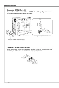
Page 28 - interface for digital audio transmission.; Serial Port Connector: JCOM1; bytes FIFOs. You can attach a serial device.
En-18 MS-7680 Mainboard English MS-7680 Mainboard English S/PDIF-Out Connector: JSP1 This connector is used to connect S/PDIF (Sony & Philips Digital Interconnect Format) interface for digital audio transmission. 11 5 V 3.VC C 2.SP DIF 1.Gro und * The MB layout in this figure is for reference on...
Page 29 - TPM Module connector: JTPM1
MS-7680 Mainboard English En-19 MS-7680 Mainboard English TPM Module connector: JTPM1 This connector connects to a TPM (Trusted Platform Module) module (optional). Please refer to the TPM security platform manual for more details and usages. 10.N o Pin 14.G roun d 8.5V Pow er 12.G roun d 6.Se rial I...
Page 30 - Parallel Port Connector: JLPT1; BIOS utility and clear the record.
En-20 MS-7680 Mainboard English MS-7680 Mainboard English Parallel Port Connector: JLPT1 This connector is used to connect an optional parallel port bracket. The parallel port is a standard printer port that supports Enhanced Parallel Port (EPP) and Extended Capa- bilities Parallel Port (ECP) mode. ...
Page 31 - Clear CMOS Jumper: JBAT1; Keep Data
MS-7680 Mainboard English En-21 MS-7680 Mainboard English Jumper Clear CMOS Jumper: JBAT1 There is a CMOS RAM on board with an external battery power supply to preserve the system configuration data. With the CMOS RAM, the system can automatically boot OS every time it is turned on. If you want to c...
Page 32 - PCIE (Peripheral Component Interconnect Express) Slot; The PCIE slot supports the PCIE interface expansion card.; PCI (Peripheral Component Interconnect) Slot; comply with PCI specifications.; Order1 Order2 Order3 Order4
En-22 MS-7680 Mainboard English MS-7680 Mainboard English Slots PCIE (Peripheral Component Interconnect Express) Slot The PCIE slot supports the PCIE interface expansion card. PCIE x16 Slot PCIE x1 Slot PCI (Peripheral Component Interconnect) Slot The PCI slot supports LAN card, SCSI card, USB card,...
Page 34 - Control Keys
En-24 MS-7680 Mainboard English MS-7680 Mainboard English Control Keys <↑><↓> Select Item <←><→> Select Screen <Enter> Select <Esc> Jumps to the Exit menu or returns to the main menu from a submenu <+><-> Change Option <F1> General Help <F6>...
Page 35 - The Menu Bar
MS-7680 Mainboard English En-25 MS-7680 Mainboard English The Menu Bar Main Menu Use this menu for basic system configurations, such as time, date etc. Advanced Use this menu to setup the items of the BIOS special enhanced features, integrated peripherals, power management and PC health status. Over...
Page 37 - Overclocking
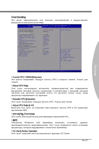
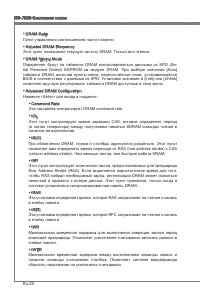
MS-7680 Mainboard English En-27 MS-7680 Mainboard English Current CPU / DRAM Frequency These items show the current clocks of CPU and Memory speed. Read-only. Adjust CPU Ratio This item controls the multiplier that is used to determine the internal clock speed of the processor relative to the extern...
Page 41 - OverSpeed Protection
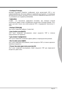
MS-7680 Mainboard English En-31 MS-7680 Mainboard English OverSpeed Protection Overspeed Protection function can monitor the current CPU draws as well as its power consumption. If it exceeds a certain level, the processor automatically re- duces its clock speed. If you want to overclock your CPU, se...
Page 42 - Product info menu : It shows the newly information of MSI product.
En-32 MS-7680 Mainboard English Software Information Take out the Driver/Utility DVD that is included in the mainboard package, and place it into the DVD-ROM drive. The installation will auto-run, simply click the driver or util- ity and follow the pop-up screen to complete the installation. The Dri...
Page 43 - Deutsch; Serie; Europe Version
Deutsch H61MU-E35/ H61M-E33/H61M-E23/H61M-P33 Serie Europe Version
Page 44 - Spezifikationen
De-2 MS-7680 Mainboard Spezifikationen Prozessoren Intel ® Sandy Bridge Prozessor für Sockel LGA1155 (Weitere CPU Informationen finden Sie unter http://www.msi.com/service/cpu-support) Chipsatz Intel ® H61 Chipsatz Speicher 2 DDR3 DIMMs unterstützen DDR3 1333/ 1066 DRAM (max. 16GB) Unterstützt die M...
Page 45 - Steckplätze
De-3 Deutsch * Wenn Sie für Bestellungen von Zubehör Teilenummern benötigen, finden Sie diese auf unserer Produktseite unter http://www.msi.com/index.php On-Board 3 Stiftleisten (H61MU-E35/ H61M-E33/ H61M-E23)/ 1 USB 2.0 Stiftleiste (H61M- P33) 1 Gehäusekontaktschalter 1 S/PDIF-Ausgang Stiftleiste 1...
Page 46 - Komponenten-Übersicht
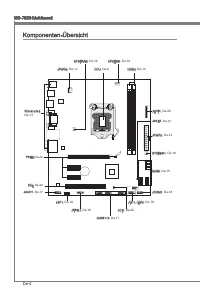
De-4 MS-7680 Mainboard Komponenten-Übersicht R ü c k t a f e l , De-13 CPU, De-6 CPUFAN, De-16 DDR3, De-10 JPWR2, De-12 PCIE, De-22 SYSFAN1, De-16 SYSFAN2, De-16 JAUD1, De-17 JSP1, De-18 JTPM1, De-19 JCI1, De-20 JBAT1, De-21 JUSB1~3, De-17 JFP1, JFP2, De-16 SATA, De-15 JPWR1, De-12 JCOM1, De-18 JLPT...
Page 47 - board sind wie nachfolgend gezeigt.; Wichtig; Schraubenlöcher
De-5 Deutsch Schraubenlöcher Wenn Sie das Mainboard zu installieren, müssen Sie das Mainboard in das Chassis in der korrekten Richtung setzen. Die Standorte von Schraubenlöchern auf dem Main- board sind wie nachfolgend gezeigt. Verweisen Sie das obige Bild, um Abstandshalter in den entsprechenden Or...
Page 49 - Justiermarkierungen
De-7 Deutsch CPU & Kühler Einbau Wenn Sie die CPU einbauen, stellen Sie bitte sicher, dass Sie auf der CPU einen Kühler anbringen, um Überhitzung zu vermeiden. Vergessen Sie nicht, etwas Siliziumwärmel- eitpaste auf die CPU aufzutragen, bevor Sie den Prozessorkühler installieren, um eine Ableitu...
Page 52 - Speicher; tionen über kompatible Bauteile finden Sie unter
De-10 MS-7680 Mainboard Speicher Diese DIMM-Steckplätze nehmen Arbeitsspeichermodule auf. Die neusten Informa- tionen über kompatible Bauteile finden Sie unter http://www.msi.com/service/test-report DDR3 240-polig, 1,5V 48x2=96 Pole 72x2=144 Pole Populationsregeln für Dual-Kanal-Speicher Im Dual-Kan...
Page 53 - Vorgehensweise beim Einbau von Speicher Modulen
De-11 Deutsch Vorgehensweise beim Einbau von Speicher Modulen Die Speichermodulen haben nur eine Kerbe in der Mitte des Moduls. Sie passen nur in einer Richtung in den Sockel.Stecken Sie das Arbeitsspeichermodul senkrecht in den DIMM-Steckplatz ein. Drücken Sie anschließnd das Arbeitsspeichermodul n...
Page 54 - Stromversorgung; Verbindung zu gewährleisten.
De-12 MS-7680 Mainboard Stromversorgung ATX 24-poliger Stromanschluss: JPWR1 Mit diesem Anschluss verbinden Sie den ATX 24-poligen Anschluss des Netzteils. Achten Sie bei dem Verbinden des ATX 24-poligen Stromanschlusses darauf, dass der Anschluss des Netzteils richtig auf den Anschluss an der Haupt...
Page 55 - Maus/Tastatur Stecker DIN ist für eine PS/2; HD-Video sowie das Audioformate der Unterhaltungselektronik.
De-13 Deutsch Rücktafel Maus/Tastatur Die Standard PS/2 ® Maus/Tastatur Stecker DIN ist für eine PS/2 ® Maus/Tastatur. USB 2.0 Anschluss Der USB 2.0 (Universal Serial Bus) Anschluss zum direkten Anschluss von USB- Geräten, wie etwa Tastatur, Maus oder weiterer USB-kompatibler Geräte. USB 3.0 Anschlu...
Page 57 - schluss kann ein S-ATA Gerät angeschlossen werden.; Datenverlusten während der Datenübertragung führt.
De-15 Deutsch Anschlüssen Serial ATA Anschluss: SATA1_2/ SATA5/ SATA6 (SATA1_2 ist optional) Der Anschluss ist eine Hochgeschwindigkeitsschnittstelle der Serial ATA. Pro An- schluss kann ein S-ATA Gerät angeschlossen werden. * Das MB-Layout in dieser Abbildung haben nur Orientierungscharakter. SATA1...
Page 58 - die Vorteile der Steuerung des CPU Lüfters zu nutzen.; LEDs des Frontpanels. JFP1 erfüllt die Anforderungen des “Intel
De-16 MS-7680 Mainboard Stromanschlüsse für Lüfter: CPUFAN,SYSFAN1~2 Die Anschlüsse unterstützen aktive Systemlüfter mit +12V. Wenn Sie den Anschluss herstellen, sollten Sie immer darauf achten, dass der rote Draht der positive Pol ist, und mit +12V verbunden werden sollte. Der schwarze Draht ist de...
Page 59 - Dieser Anschluss entspricht den Richtlinien des Intel; panels. Der Anschluss entspricht den Richtlinien des “ Intel
De-17 Deutsch USB Vorderanschluss: JUSB1~3 (JUSB2~3 sind optional) Dieser Anschluss entspricht den Richtlinien des Intel ® I/O Connectivity Design Guide. Er ist bestens geeignet, Hochgeschwindigkeits- USB- Peripheriegeräte anzuschließen, wie z.B. USB Festplattenlaufwerke, Digitalkameras, MP3-Player,...
Page 60 - tragung digitaler Audiodaten verwendet.; Serieller Anschluss: JCOM1
De-18 MS-7680 Mainboard S/PDIF-Ausgang: JSP1 Die S/PDIF (Sony & Philips Digital Interconnect Format) Schnittstelle wird für die Über- tragung digitaler Audiodaten verwendet. 11 5 V 3.VC C 2.SP DIF 1.Gro und * Das MB-Layout in dieser Abbildung haben nur Orientierungscharakter. S/PDIF-Ausgang Slot...
Page 61 - en Sie bitte dem TPM Plattform Handbuch.
De-19 Deutsch TPM Anschluss: JTPM1 Dieser Anschluss wird für das optionale TPM Modul (Trusted Platform Module) ver- wendt. Weitere Informationen über den Einsatz des optionalen TPM Modules entnehm- en Sie bitte dem TPM Plattform Handbuch. 10.N o Pin 14.G roun d 8.5V Pow er 12.G roun d 6.Se rial IR Q...
Page 62 - gerufen und die Aufzeichnung gelöscht werden.
De-20 MS-7680 Mainboard Parallele Schnittstelle: JLPT1 Die Parallele Schnittstelle ist eine Standard Druckerschnittstelle, die ebenso als En- hanced Parallel Port (EPP) und als Extended Capabilities Parallel Port (ECP) betrieben werden kann. 10.G roun d 14.G roun d 8.LP T_S LIN# 12.G roun d 6.PIN IT...
Page 64 - PCIE (Peripheral Component Interconnect Express) Steckplatz; karten aufnehmen, die mit den PCI-Spezifikationen konform sind.; Folge1 Folge2 Folge3 Folge4
De-22 MS-7680 Mainboard Steckplätze PCIE (Peripheral Component Interconnect Express) Steckplatz Der PCIE-Steckplatz unterstützt eine Erweiterungskarte mit der PCIE-Schnittstelle. PCIE x16-Steckplatz PCIE x1-Steckplatz PCI (Peripheral Component Interconnect) Steckplatz Der PCI-Steckplatz kann LAN-Kar...
Page 65 - Sie zum Aufruf des BIOS SETUP aufgefordert werden.; te - 5te Stelle bezeichnen die Modelnummer.; Aufruf des BIOS Setups; F11 drücken um das Bootmenü zu erreichen)
De-23 Deutsch BIOS Setup Dieses Kapitel enthält Informationen über das BIOS Setup und ermöglicht es Ihnen, Ihr System optimal auf Ihre Anforderungen einzustellen. Notwendigkeit zum Aufruf des BIOS besteht, wenn: Während des Bootvorgangs des Systems eine Fehlermeldung erscheint und Sie zum Aufruf des...
Page 67 - Die Menüleise
De-25 Deutsch Die Menüleise Main Menu In diesem Menü können Sie die Basiskonfiguration Ihres Systems anpassen, so z.B. Uhrzeit, Datum usw. Advanced Verwenden Sie dieses Menü, um eigene weitergehende Einstellungen an Ihrem System, integrierte Peripheriegeräte, die Stromsparfunktionen und der PC-Gesun...
Page 74 - Sicherheits-Menü : Es bietet die nützliche Antivirenprogramm.; für bessere System Leistung zu erhalten.
De-32 MS-7680 Mainboard Software-Information Die im Mainboard-Paket enthaltene DVD enthält alle notwendigen Treiber. Um die Installation automatisch laufen zu lassen, klicken Sie einfach den Treiber oder Utiltiy und folgen Sie dem Pop-Up Schirm, um die Installation durchzuführen. Der Treiberge- brau...
Page 75 - Français; Séries
Français H61MU-E35/ H61M-E33/H61M-E23/H61M-P33 Séries Europe version
Page 76 - Spécifications
Fr-2 Carte mère MS-7680 Spécifications Processeurs Supportés Intel ® Sandy Bridge processeurs dans le paquet LGA1155 (Pour plus d'information sur le CPU, veuillez visiter http://www.msi.com/service/cpu-support) Jeu de puces Puces Intel ® H61 Mémoire supportée 2 DDR3 DIMMs supportent DDR3 1333/ 1066 ...
Page 77 - Emplacements
Fr-3 Français * Si vous désirez acheter des accessoires et vous avez besoin de numéros des pièces, vous pouvez chercher sur la page website et trouver les détails sur notre adresse ci- dessous http://www.msi.com/index.php Connecteurs intégrés 3 connecteurs USB 2.0 (H61MU-E35/ H61M-E33/ H61M-E23)/ 1 ...
Page 78 - Guide Rapide Des Composants
Fr-4 Carte mère MS-7680 Guide Rapide Des Composants Panneau arrière, Fr-13 CPU, Fr-6 CPUFAN, Fr-16 DDR3, Fr-10 JPWR2, Fr-12 PCIE, Fr-22 SYSFAN1, Fr-16 SYSFAN2, Fr-16 JAUD1, Fr-17 JSP1, Fr-18 JTPM1, Fr-19 JCI1, Fr-20 JBAT1, Fr-21 JUSB1~3, Fr-17 JFP1, JFP2, Fr-16 SATA, Fr-15 JPWR1, Fr-12 JCOM1, Fr-18 ...
Page 79 - châssis qui entraînerait un court circuit à la carte mère.
Fr-5 Français Trous Taraudés Quand vous installez la carte mère, il faut déposer la carte dans le châssis en bonne position. La situation des trous taraudés sont montrée dans la figure ci-dessous. Veuillez vous référer à la figure pour installer le support dans une position appropriée sur le châssis...
Page 81 - Installation du CPU et son ventilateur; Clé d’alignement
Fr-7 Français Installation du CPU et son ventilateur Quand vous installez le CPU, assurez-vous que le CPU soit équipé d’un ventilateur de refroidissement attaché sur le dessus pour éviter la surchauffe. Méanmoins, n’oubliez pas d’appliquer une couche d’enduit thermique sur le CPU avant d’installer l...
Page 84 - Mémoire; d’informations sur les composants compatibles, veuillez visiter; du
Fr-10 Carte mère MS-7680 Mémoire Ces slots DIMM sont destinés à installer les modules de mémoire. Pour plus d’informations sur les composants compatibles, veuillez visiter http://www.msi.com/service/test-report DDR3 240-pin, 1.5V 48x2=96 pin 72x2=144 pin Règle de population en mode double-canaux En ...
Page 85 - Installation des modules de mémoire; du slot DIMM sur les côtés.; inséré dans le slot du DIMM.
Fr-11 Français Installation des modules de mémoire Le module de mémoire possède une seule encoche en son centre et ne s’adaptera que s’il est orienté de la mqnière convenable.Insérez le module de mémoire à la verticale dans le slot du DIMM. Poussez-le en- suite jusqu’à l’extrémité dorée du module de...
Page 86 - Connecteurs d’alimentation; Connecteur d’alimentation ATX 24-pin : JPWR1; tions ATX pour garantir une opération stable de la carte mère.
Fr-12 Carte mère MS-7680 Connecteurs d’alimentation Connecteur d’alimentation ATX 24-pin : JPWR1 Ce connecteur vous permet de connecter l’alimentation ATX 24-pin. Pour cela, as- surez-vous que la prise d’alimentation est bien positionnée dans le bon sens et que les goupilles soient alignées. Enfonce...
Page 87 - l’audio digital de multi-canaux sur le câble simple en plus
Fr-13 Français Panneau arrière Souris/Clavier Le standard connecteur de souris/clavier DIN de PS/2 ® est pour une souris ou un clavier de PS/2 ® . Port USB 2.0 Le port USB 2.0 (Universal Serial Bus) sert à brancher des périphériques USB tels que le clavier, la souris, ou d’autres périphériques compa...
Page 89 - être relié à un appareil de série ATA.; pourraient se produire pendant la transmission
Fr-15 Français Connecteurs Connecteur Sérial ATA : SATA1_2/ SATA5/ SATA6 (SATA1_2 est en option) Ce connecteur est un port d’interface de série ATA haut débit. Chaque connecteur peut être relié à un appareil de série ATA. Important Veuillez ne pas plier le câble de série ATA à 90°. Autrement des per...
Page 90 - afin de contrôler le ventilateur de l’unité centrale.; ponibles pour CPUFAN.
Fr-16 Carte mère MS-7680 Connecteur d’alimentation du ventilateur : CPUFAN,SYSFAN1~2 Les connecteurs de courant du ventilateur supportent le ventilateur de refroidissement du système avec +12V. Lors du branchement des fils aux connecteurs, faites toujours en sorte que le fil rouge soit le fil positi...
Page 91 - panneau avant Intel; tout dommage possible.; Connecteur audio panneau avant : JAUD1
Fr-17 Français Connecteur USB avant : JUSB1~3 (JUSB2~3 sont en option) Ce connecteur est conforme au guide de conception de la connectivité Entrée/sortie du panneau avant Intel ® , il est idéal pour relier les périphériques d’interface USB à haut débit tels les disques durs externes, les appareils p...
Page 92 - Format) pour une transmission audio numérique.; Connecteur de port sérial : JCOM1
Fr-18 Carte mère MS-7680 Connecteur S/PDIF-Out : JSP1 Ce connecteur sert à connecter l’interface S/PDIF (Sony & Philips Digital Interconnect Format) pour une transmission audio numérique. 11 5 V 3.VC C 2.SP DIF 1.Gro und * Le schéma de carte mère dans la figure n’est qu’à titre de référence. Sup...
Page 93 - Connecteur du Module TPM : JTPM1
Fr-19 Français Connecteur du Module TPM : JTPM1 Ce connecteur est rélié à TPM (Trusted Platform Module) Module (en option). Veuillez vous référer au manuel de TPM plat-forme (en option) de sécurité pour plus de détails et d’utilisations. 10.N o Pin 14.G roun d 8.5V Pow er 12.G roun d 6.Se rial IR Q ...
Page 95 - Cavalier d’effacement CMOS : JBAT1
Fr-21 Français Cavalier Cavalier d’effacement CMOS : JBAT1 Il y a un CMOS RAM intégré, qui possède un bloc d’alimentation alimenté par une bat- terie externe, destiné à conserver les données de configuration du système. Avec le CMOS RAM, le système peut lancer automatiquement le système d’exploitati...
Page 96 - Emplacement PCIE (Peripheral Component Interconnect Express)
Fr-22 Carte mère MS-7680 Emplacements Emplacement PCIE (Peripheral Component Interconnect Express) L’emplacement PCIE supporte la carte d’extension d’Interface PCIE. Emplacement PCIE x16 Emplacment PCIE x1 Emplacement PCI (Peripheral Component Interconnect) L’emplacement PCI supporte la carte LAN, l...
Page 97 - version BIOS. Elle est généralement sous la forme :; Entrée dans le paramétrage
Fr-23 Français Réglage BIOS Ce chapitre donne des informations concernant le programme de réglage du BIOS et vous permet de configurer le système pour obtenir des performances d’utilisation opti- mum. Vous aurez peut-être besoin de lancer le programme de réglage lorsque : Un message d’erreur apparaî...
Page 99 - La barre menu
Fr-25 Français La barre menu Main Menu Utilisez ce menu pour les configurations du système de base, tel que l’heure, la date. Advanced Utilisez ce menu pour régler les objets des fonctions améliorées spéciales du BIOS, les périphériques intégrés, la gestion d’alimentation et l’état de santé de l’ord...
Page 106 - Information Logiciel; haitez pour activer le dispositif.; meilleure performance du système.
Fr-32 Carte mère MS-7680 Information Logiciel Sortez le DVD Pilote/ Service, qui est inclus dans la boîte de la carte mère et placez-le dans le DVD-ROM. L’installation va automatiquement se déclencher, cliquez sur le pi- lote ou sur l’utilitaire et suivez le pop-up de l’écran pour accomplir l’instal...
Page 107 - Русский
Русский СерияH61MU-E35/ H61M-E33/H61M-E23/H61M-P33 Europe version
Page 109 - Слоты
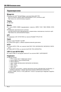
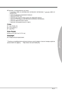
MS-7680 Системная плата Русский Ru-3 MS-7680 Системная плата Русский * Помощь в приобретении дополнительных аксессуаров и поиске номера изделия можно найти по адресу http://www.msi.com/index.php Разъемы, установленные на плате 3 разъема USB 2.0 (H61MU-E35/ H61M-E33/ H61M-E23)/ 1 разъем USB 2.0 (H61M...
Page 111 - Внимание
MS-7680 Системная плата Русский Ru-5 MS-7680 Системная плата Русский Отверстия для винтов При установке системной платы нужно вставить её в корпус в правильном направлении. Размещения отверстий для винтов показаны ниже. Следуйте указаниям выше указанно для установки держателей в правильном месте в к...
Page 113 - Установка процессора и вентилятора; Ключ для
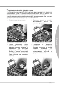
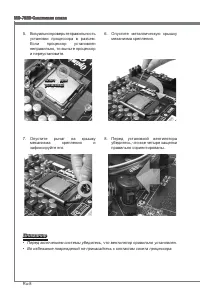
MS-7680 Системная плата Русский Ru-7 MS-7680 Системная плата Русский Установка процессора и вентилятора Во избежание перегрева при работе обязательно установите вентилятор процессора. Одновременно, чтобы улучшить теплоотвод, убедитесь в том, что нанесён слой теплопроводящей пасты на процессоре перед...
Page 117 - Установка модулей памяти
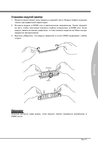
MS-7680 Системная плата Русский Ru-11 MS-7680 Системная плата Русский Установка модулей памяти Модули памяти имеют одну прорезь в средней части. Модуль войдет в разьем только при правильной ориентации.Вставьте модуль в DIMM слот в вертикальном направлении. Затем нажмите на него, чтобы золоченые конт...
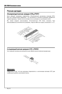
Page 118 - Вы также можете использовать 20-контактный ATX блок питания. При; стабильной работы системной платы.
Ru-12 MS-7680 Системная плата Русский MS-7680 Системная плата Русский Разъем питания 24-контактный разъем питания ATX: JPWR1 Этот разъем позволяет подключить 24-контактный коннектор питания ATX. Для его подключения убедитесь, что коннектор и контакты разъема правильно сориентированы. Затем плотно вс...
Page 119 - Стандартные разъемы DIN PS/2; многоканальное цифровое аудио.
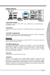
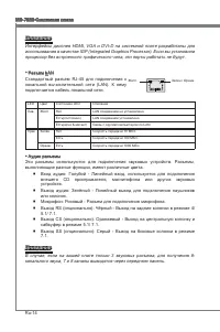
MS-7680 Системная плата Русский Ru-13 MS-7680 Системная плата Русский Задняя панель Порт мыши/клавиатуры Стандартные разъемы DIN PS/2 ® для подключения мыши/клавиатуры с интерфейсом PS/2 ® . Порт USB 2.0 Порт USB 2.0 позволяет подключать такие USB устройства, как клавиатура, мышь и т.д. Порт USB 3.0...
Page 121 - могут возникнуть потери данных при передаче.
MS-7680 Системная плата Русский Ru-15 MS-7680 Системная плата Русский Коннекторы Разъем Serial ATA: SATA1_2/ SATA5/ SATA6 (SATA1_2 опционально) Данный разъем является высокоскоростным портом интерфейса Serial ATA. Любой разъем Serial ATA может соединяться с одним устройством Serial ATA. * Компоненты...
Page 122 - руководству Intel
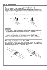
Ru-16 MS-7680 Системная плата Русский MS-7680 Системная плата Русский Разъем питания вентиляторов: CPUFAN,SYSFAN1~2 Разъемы питания вентиляторов поддерживают вентиляторы с питанием +12В. При подключении необходимо помнить, что красный провод подключается к шине +12В, черный - к земле GND. Если на си...
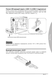
Page 123 - Разъем, соответствует спецификации Intel; ВНИМАНИЕ, во избежание повреждений, контакты VCC и GND должны быть; Выносной разъем аудио: JAUD1; панели и соответствует руководству Intel
MS-7680 Системная плата Русский Ru-17 MS-7680 Системная плата Русский Разъем USB передней панели: JUSB1~3 (JUSB2~3 опционально) Разъем, соответствует спецификации Intel ® I/O Connectivity Design и преднозначен для подключения высокоскоростных периферийных устройств, таких как USB HDD, цифровые камер...
Page 124 - Разъем последовательного порта: JCOM1; подключить последовательное устройство.
Ru-18 MS-7680 Системная плата Русский MS-7680 Системная плата Русский Разъем S/PDIF-Out: JSP1 Этот разъем используется для подключения интерфейса S/PDIF (Sony & Philips Digital Interconnect Format) для передачи звука в цифровом формате. 11 5 V 3.VC C 2.SP DIF 1.Gro und * Компоненты системной пла...
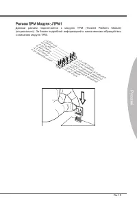
Page 125 - Разъем TPM Модуля: JTPM1; Данный разъем подключается к модулю TPM (Trusted Platform Module)
MS-7680 Системная плата Русский Ru-19 MS-7680 Системная плата Русский Разъем TPM Модуля: JTPM1 Данный разъем подключается к модулю TPM (Trusted Platform Module) (опционально). За более подробной информацией и назначениями обращайтесь к описанию модуля TPM. 10.N o Pin 14.G roun d 8.5V Pow er 12.G rou...
Page 126 - Разъем параллельного порта: JLPT1
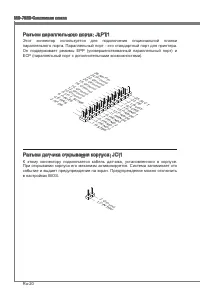
Ru-20 MS-7680 Системная плата Русский MS-7680 Системная плата Русский Разъем параллельного порта: JLPT1 Этот коннектор используется для подключения опциональной планки параллельного порта. Параллельный порт - это стандартный порт для принтера. Он поддерживает режимы EPP (усовершенствованный параллел...
Page 127 - Перемычка очистки CMOS: JBAT1
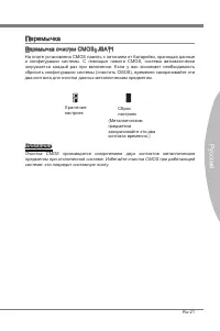
MS-7680 Системная плата Русский Ru-21 MS-7680 Системная плата Русский Перемычка Перемычка очистки CMOS: JBAT1 На плате установлена CMOS память с питанием от батарейки, хранящая данные о конфигурации системы. С помощью памяти CMOS, система автоматически загружается каждый раз при включении. Если у ва...
Page 128 - Слот PCIE (Peripheral Component Interconnect Express); Слот PCIE поддерживает карты расширения интерфейса PCIE.; Слот PCI (Peripheral Component Interconnect); карты расширения, которые соответствуют спецификации PCI.; Приказ1 Приказ2 Приказ3 Приказ4
Ru-22 MS-7680 Системная плата Русский MS-7680 Системная плата Русский Слоты Слот PCIE (Peripheral Component Interconnect Express) Слот PCIE поддерживает карты расширения интерфейса PCIE. PCIE x16 слот PCIE x1 слот Слот PCI (Peripheral Component Interconnect) Слот PCI позволяет установить карты LAN, ...
Page 130 - Клавиши управления
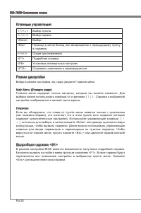
Ru-24 MS-7680 Системная плата Русский MS-7680 Системная плата Русский Клавиши управления <↑><↓> Выбор пункта <←><→> Выбор экрана <Enter> Выбор <Esc> Переход в меню Выход или возвращение к предыдущему пункту в подменю <+><-> Опция для изменения <F1&g...
Page 131 - Строка Меню
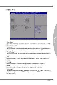
MS-7680 Системная плата Русский Ru-25 MS-7680 Системная плата Русский Строка Меню Main Menu Это меню позволяет установить основные параметры конфигурации системы (дату, время и т.п.). Advanced Это меню используется для настройки специальных функций BIOS, периферийных устройств, управления питанием и...
Page 132 - умолчанию для оптимальной производительности системы.
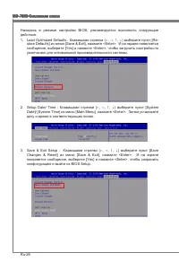
Ru-26 MS-7680 Системная плата Русский MS-7680 Системная плата Русский Находясь в режиме настройки BIOS, рекомендуется выполнить следующие действия. Load Optimized Defaults : Клавишами стрелки (←, →, ↑, ↓) выберите пункт [Re- store Defaults] из меню [Save & Exit], нажмите <Enter>. И на экра...
Page 138 - Установите драйверы для подключения необходимых устройств.; BIOS, которые позволят улучшить производительность системы.
Ru-32 MS-7680 Системная плата Русский Сведения о программном обеспечении Установите в привод диск Driver/Utility (Драйверы и утилиты) из комплекта поставки системной платы. Автоматически запустится инсталляция. Нажмите на название драйвера/ утилиты и следуйте инструкциям на экране для завершения инс...


 MSI GX60 DESTROYER User Manual
 MSI GX70 DESTROYER User Manual
 MSI H55M-E21 User Manual
 MSI H55M-E33 User Manual
 MSI H55M-P33 User Manual
-User-Manual/webp/1.webp) MSI H61I-E35 (B3) User Manual
MSI H61I-E35 (B3) User Manual MSI H61M-E33/W8 User Manual
 MSI H61M-P20 (G3) User Manual
-User-Manual/webp/1.webp) MSI H61M-P21 (B3) User Manual
MSI H61M-P21 (B3) User Manual MSI H61M-P25 (B3) User Manual
-User-Manual/webp/1.webp) MSI H61M-P31 (G3) User Manual
MSI H61M-P31 (G3) User Manual