Maytag 11-06-00- User Manual
Maytag 11-06-00– User Manual, read for free online in PDF format. We hope this helps you resolve any issues you may have. If you have further questions, please contact us through the contact form.


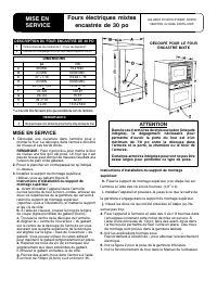
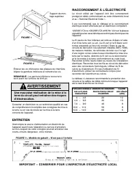
Table of Contents:
- Page 2 – IMPORTANT -- SAVE FOR LOCAL ELECTRICAL INSPECTOR’S USE; Improper installation of the grounding; FIGURE 2
- Page 3 – NOTAS; INSTALACIÓN; CORTE COMBINADO DEL; INSTRUCCIONES; Hornos eléctricos
- Page 4 – CONEXIONES ELÉCTRICAS; IMPORTANTE: CONSERVE ESTAS INSTRUCCIONES PARA USO DEL INSPECTOR; ADVERTENCIA; SERVICIO; FIGURA 1; FIGURA 2
- Page 5 – REMARQUES; MISE EN SERVICE; ATTENTION; DESCRIPTION DU FOUR ENCASTRÉ DE 30 PO; MISE EN
- Page 6 – IMPORTANT -- CONSERVER POUR L’INSPECTEUR D’ÉLECTRICITÉ LOCAL; AVERTISSEMENT; Une mauvaise réalisation de la mise à la
NOTES
Z
Do not block air intake slots along bottom of oven.
INSTALLATION
1.
Cut hole in cabinet to mount oven. Cutout in
cabinet should be level and straight.
NOTE:
There are no provisions to level the unit
after it is installed. An oven that is not level could
cause poor baking results.
2.
Install plywood floor as shown above.
3.
Install top mounting bracket -- also refer to
template.(figure 3)
Top bracket mounting installation
instructions:
a.
Before installing unit into the cabinet, open
microwave door, remove the two upper screws in
the trim kit holding the top mounting bracket (see
figure 1
next page) and set the bracket and
screws to the side.
b.
Using scissors cut along the cut line on the
template (provided).
c.
Find the center of the cabinet cutout.
d.
Align the template ”center of opening” to the
center of the cabinet cutout making sure the top
of the cabinet cutout corresponds with the
template ”top of opening” indicator line. Tape may
be used to hold the template temporarily in place.
e.
Locate and mark screw holes (A) at both
ends, 2 each side, of template.
f.
Remove template and set it to the side.
g.
Drill pilot holes into cabinet using 7/64” or
#35 drill bit.
h.
Install top mount bracket (from step 3a) to
cabinet with the provided wood screws. (1/2” X 4)
8101P744-60
(11-06-00)
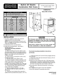
CAUTION
For European style cabinets (flush front) the required
clearance for operation of the oven door is minimum
spacing of 7/8
″
between the cutout and the door, hinge
or drawer of the cabinet.
Some built-in cabinets may not be wide enough, due
to their construction, to allow this installation.
COMBINATION
WALLOVEN CUTOUT
30
″
WALL OVEN DESCRIPTION
1
1-1/4
″
Dia. Conduit Access Hole*
2
5/8
″
Plywood Floor (Must Support 250 lbs.)
DIMENSIONS
in
cm
A
30 MIN
76.20 MIN
B
24 MIN
60.96 MIN
C
47 + 1/16
119.38 + .16
D
24 MIN
60.96
E
28-1/2 + 1/16
72.39 + .16
F
47-5/8
120.97
G
29-3/4
75.57
H
24-7/16
62.07
I
4 to 20
10.2 to 50.8
* Hole must be cut as close to corner of cabinet as possible.
INSTALLATION
INSTRUCTIONS
Built-In 30
″
Electric
Combination Wall Ovens
403 WEST FOURTH STREET, NORTH
NEWTON, IA 50208
Top bracket mounting installation instructions:
(continued)
i.
Install and push unit in until trim frame engages with top
mount bracket.
j.
Drive two screws that were removed in step (a) Do not
over tighten the screws
.
4.
Attach unit to the cabinet with 4 No. 8, flat head screws
supplied inside of envelope containing these instructions.
Pre--drill holes in cabinet for attachment screws using 1/8,
drill. Oven mounting holes are provided in side trim.
5.
See instructions ”Electrical Connections” for electrical
hook--up.
6.
See
figure 2
next page for lower trim installation.
7.
See User’s Manual for operating instructions.
"Loading the manual" means you need to wait until the file loads and becomes available for online reading. Some manuals are very large, and the time they take to appear depends on your internet speed.
Other Manuals for Maytag 11-06-00
Summary
ELECTRICAL CONNECTIONS Unit to be properly circuit protected and wired according to local electrical code and National Electrical Code. It is advisable that the electrical wiring and hookup be accomplished by a competent electrician. 120/240 VAC or 120/208 VAC 60 Hz. See serial plate on each unit fo...
NOTAS Z No obstruya las ranuras de entrada de aire de la parte inferior del horno. INSTALACIÓN 1. Corte un orificio en el gabinete para montar el horno. El hueco del gabinete debe estar bien nivelado y enderezado. NOTA: No hay estipulaciones para nivelar la unidad después de que esté instalada. Un h...
CONEXIONES ELÉCTRICAS El circuito de la unidad debe estar protegido y cableado correctamente y de acuerdo con los códigos eléctricos locales y con el Código Eléctrico Nacional. Es recomendable que el cableado y las conexiones eléctricas las realice un electricista competente. 120/240 VCA o 120/208 V...